Tip: Start typing in the input box for immediate search results.Can't find what you're looking for? Submit a support request here.
Coldworking Analysis Overview
Coldworking Analysis in StressCheck
StressCheck provides a unique capability for simulating the effects of coldworking on a single hole without reverse plasticity (for multiple holes and/or to account for reverse plasticity, refer to coldworking via incremental plasticity theory). This capability is based on the deformation theory of plasticity and utilizes superposition. The cold-worked body is represented by a plane stress or plane strain model. A detailed description follows.

Coldworking Simulation Process

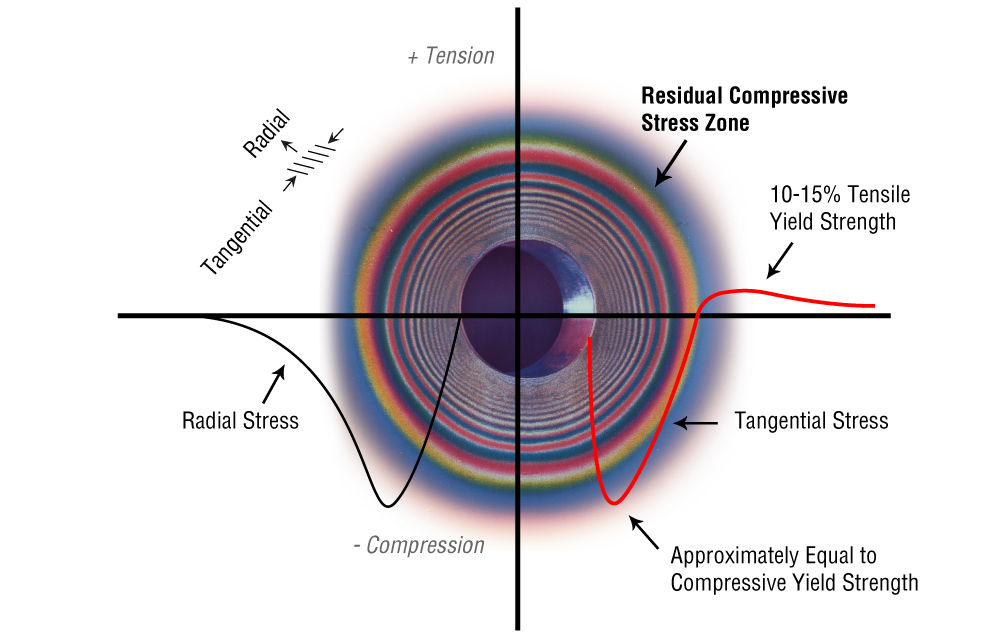
When a mandrel is introduced into a hole in a structural component (Figure 2), a plastic region develops around the hole, the size of which depends on the interference level, the material properties of the mandrel, and the material properties and topological configuration of the component. The extent of the plastic zone can be accurately determined using the deformation theory of plasticity. When the mandrel is removed, the traction-free condition in the radial direction around the hole is restored, and residual stresses are locked into the component. The below image in Figure 3 demonstrates a residual stress resulting from a coldworking process:

One important limitation of the deformation theory of plasticity is that unloading events are not represented, and therefore the residual stresses must be determined indirectly by superposition. When an external load is subsequently applied to the part, the stress pattern will be affected by the residual stresses created during the cold-working operation, and again a superposition procedure must be used.
The superposition procedure implemented within the Coldwork option can be initiated after the linear analysis of the component for the user’s specified loads and constraints was completed. Once the hole to be cold-worked is identified, the following analyses are performed:
- An elastic-plastic analysis of the component when the mandrel is introduced into the hole.
- A linear analysis of the component with the specified constraints and loaded with a self-equilibrated radial traction around the cold-worked hole, the distribution of which is determined from the elastic-plastic analysis indicated above.
- When the mandrel is removed, the traction-free condition must be restored in the radial (normal) direction around the cold-worked hole.

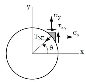
The traction distribution around the hole when the mandrel is still in place is computed from the elastic-plastic solution:

where σx, σy and τxy are the nonlinear stress components around the hole in the global coordinate system. The effect of removing the mandrel is accounted for by solving a linear problem with the cold-worked hole loaded with the radial traction distribution induced by the mandrel. The traction distribution given by (4) is approximated by a Fourier series expansion in the form:

where TR is an approximation of TNL, θ is the angle measured from a polar coordinate system located at the center of the hole, and the coefficients an and bn are computed from:

The integrated traction is self-equilibrated, provided a1 = b1 = 0, therefore this constraint is enforced. The expansion includes 10 terms, and TNL is computed at 360 equally spaced points around the hole. The quality of fit is determined by computing the least squares error between the actual and approximating functions as follows:

Once the traction distribution is computed, the program performs a linear analysis of the component with the originally specified constraints and when the only applied loading is the traction around the hole given by Eq. (5). After completion of the Coldwork analysis, the following information is available:
- The elastic-plastic solution due to the cold-working operation.
- The solution corresponding to the residuals after the mandrel was removed.
- The solution of the problem with the specified loads and the residual stresses combined.
The applicable stress-strain laws include elastic-perfectly plastic, elastic-strain hardening and Ramberg-Osgood laws. The von Mises yield criterion in the context of plane stress or plane strain conditions is used.
Because the resulting stress field is determined by superposition, reverse plasticity cannot be accounted for by the model. StressCheck issues a warning message if in a particular application reverse plasticity is detected. Reverse plasticity is understood to mean that upon removal of the mandrel a compressive zone develops in which the maximum equivalent plastic strain exceeds a tolerance, the value of which is 0.2%.
Coldworking Solver Options
The component to be analyzed is defined by providing its topology, thickness, material properties, constraints and loading. The material properties of the component must be defined as elastic-plastic. Also, the linear material properties of the mandrel used in the cold working operation have to be provided.
Execute a linear analysis and obtain a sequence of solutions using p-extension so that the quality of the solution can be estimated. The estimated relative error in energy norm should be small, typically below 5% (preferably below 1%) before proceeding with the rest of the analysis.
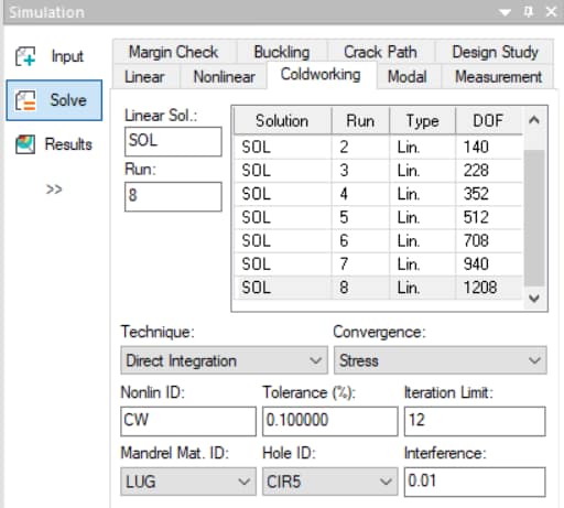
Next, select the Coldworking tab in the Solve dialog and proceed as follows:
Linear Solution List
Click on the linear solution which is to be the starting solution for the coldworking analysis (Linear Sol:). The solution name, run number, type, and associated degrees of freedom (DOF) appear in the scroll window of the dialog box. The corresponding discretization will remain fixed in the course of the coldworking solution process.
Nonlinear ID
Enter a name for the nonlinear solution (Nonlin ID:) which is different from the name of the linear solution (Linear Sol:). For example, you can modify the name of the linear solution by adding the letters NL (for nonlinear).
Convergence
Select the Convergence option (Stress is recommended for Coldworking) and the allowable tolerance (1% or less).
Technique
Choose the “Direct” integration procedure.
Iteration Limit
Enter the number of iteration cycles into the Iteration Limit field. StressCheck will stop when the iteration limit is reached, except when the specified error tolerance is reached first. The Coldworking analysis is completed even if convergence was not achieved after the specified number of iterations. If the error is not small enough, provide a higher value for the iteration limit and execute the coldworking analysis again.
Hole ID
The name of the circle corresponding to the hole to be cold-worked (e.g. CIR5). You can click on the combo box next to Hole ID, and select from the list of circles available. The one selected will be highlighted on the main display area.
Interference
Enter the diametric interference level, which is the difference between the diameter of the mandrel and the diameter of the hole. You can enter a numerical value or the name of a previously defined parameter into the field.
Mandrel Material ID
Enter the material ID given to the mandrel in the material input box. If you did not define a material property for the mandrel, select Class: Material from the Main Menu Bar and provide the material ID, modulus of elasticity and Poisson’s ratio. The scrolling list next to Mandrel Material ID contains a list of all materials defined in the current session.
Only linear isotropic material properties can be specified for the mandrel. The input material coefficients are used to compute the radial spring stiffness of the mandrel (Kr) from the following expression:

Here, E and v are the modulus of elasticity and Poisson’s ratio of the mandrel material, and D is the diameter of the hole.
Executing a Coldworking Analysis
Next, complete the solution options as follows:
- Execute: Initialize
- Run Mode: Automatic
- Method: Direct.
- Click on the Solve button to start the coldwork analysis.
Note: The use of symmetry conditions for the cold-worked hole are not possible in the current implementation.
 Serving the Numerical Simulation community since 1989
