Tip: Start typing in the input box for immediate search results.Can't find what you're looking for? Submit a support request here.
Bulk Residual Stress (BRS) Overview
Introduction
Many metal forming or coldworking processes can induce bulk residual stresses (BRS) throughout the volume of material which impact distortion, fatigue life, etc. StressCheck provides a load module for including BRS in linear analysis to predict these effects.

BRS due to the metal forming process are by definition in equilibrium. As material is removed by a machining process, the residual stresses must redistribute to compensate so that an equilibrated state is maintained. The redistribution is accompanied by distortion of the part as stored energy is released. For a known initial residual stress state on a part that is to be machined, StressCheck can solve for both the distortion caused by machining and for the resulting redistributed residual stresses. For a known residual stress state on a final part geometry (either imported or computed with StressCheck), StressCheck can include the residual stresses in computations of the J-integral or stress intensity factors for arbitrarily shaped cracks in the part subjected to residual stresses.
Specifying BRS Data
Residual stresses can be computed in StressCheck, imported from a simulation in another analysis tool, or specified with spatial formulae.
Computing BRS in StressCheck for a BRS Load Assignment
The material nonlinear solver can be used in combination with incremental plasticity theory to predict a residual stress distribution, and then the residual stresses from the resulting plasticity solution can be converted to a state which can be used by the BRS load assignment.
1. Define a Part containing all elements to be solved with the incremental plasticity nonlinear analysis. This is done on the Parts tab of the Input dialog.
2. Define a Solution Configuration which includes the solution ID as Active and which references the Part defined in step 1. This is done on the Configurations subtab of the Solution ID tab in the Input dialog. Be sure to select the Part in the Part dropdown.
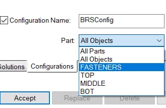
3. When solving the linear solution which precedes the nonlinear solution, choose the Solution Configuration in the “Solution” dropdown of the Solve dialog as shown below. This will make the linear solution associated with the Part defined in step 1.
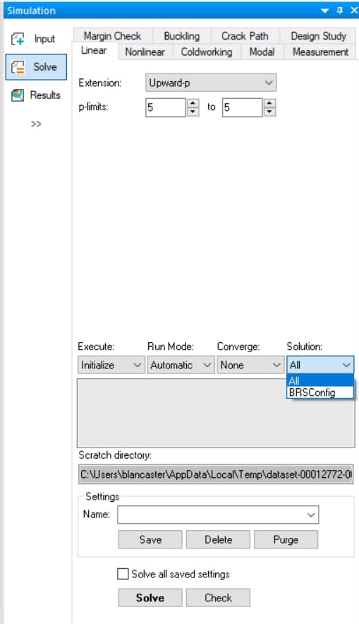
4. Solve the incremental plasticity nonlinear solution normally, beginning with the linear solution which references the Part through its solution configuration.
5. In the Edit Menu, choose Bulk Residual Stress to open the Bulk Residual Stress dialog. The “Map Solution” tab will be used to convert the incremental plasticity solution to a solution which is usable by a BRS load assignment.
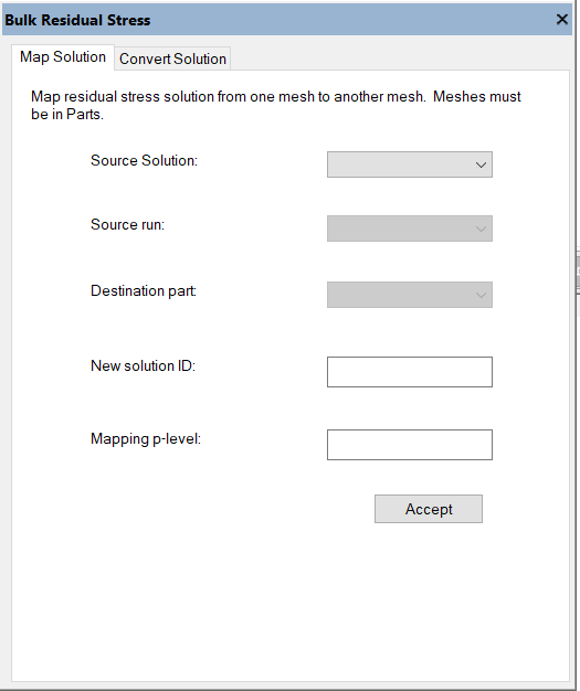
6. For Source Solution choose the incremental plasticity solution corresponding to residual stresses (this should have no external loads in order to be a residual stress state).
7. Choose the run with highest DOF associated with the solution.
8. Choose the Part defined in step 1 as the target destination part of the converted solution.
- The solution can be mapped to any part even if the domain is not the same. For example, to use the residual stresses on another domain which represents the machined shape, define an additional part containing all elements of the machined shape, and choose this as the target destination part.
9. Enter a new solution ID to represent the new mapped/converted solution.
10. Specify a mapping p-level. This will be the order of the shape functions which describe the residual stress solution on the elements of the destination part.
- It is recommended to use the same p-level as the incremental plasticity solution if the destination part is the same as the part used for the plasticity solution.
- If the part is a different part containing a different domain, choose a p-level which will well-represent the solution based on the mesh density. This involves an inverse mapping operation which can take significantly more time for higher mapping p-levels.
11. Press Accept to begin the mapping process.
12. The end result will be a solution associated with the destination part with the given solution ID. This solution can be used in a BRS load assignment (described in the next section).
Combining Multiple Solved Linear Load Cases for a BRS Load Assignment
Similar to the process described for mapping a nonlinear solution for use in a BRS load, one or more linear stress solutions can be combined and converted to a solution which can be used in a BRS load. This is only applicable to automeshes with isoparametric mapping.
1. Define a Part containing all elements to be solved. This is done on the Parts tab of the Input dialog.
2. Define a Solution Configuration which includes all desired solution IDs with the various load cases as Active and which references the Part defined in step 1. This is done on the Configurations subtab of the Solution ID tab in the Input dialog. Be sure to select the Part in the Part dropdown.
3. When solving the linear solution, choose the Solution Configuration in the “Solution” dropdown of the Solve dialog. This will make the linear solution associated with the Part defined in step 1.
4. In the Edit Menu, choose Bulk Residual Stress to open the Bulk Residual Stress dialog. The “Convert Solution” tab will be used to linearly combine and scale the available solved load cases, converting them to a single solution which is usable by a BRS load assignment.
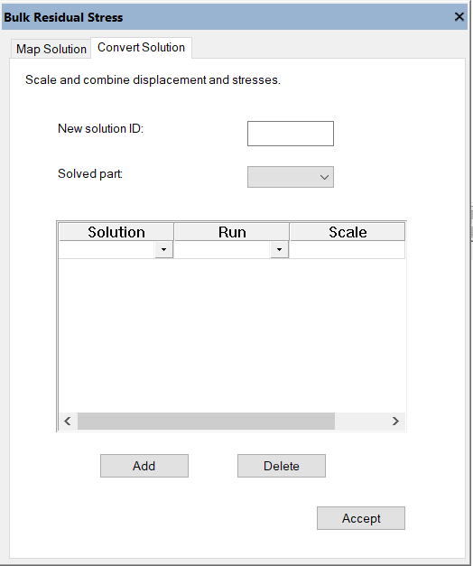
5. Enter a New Solution ID which will represent the combined solution.
6. Choose the Solved Part (created in step 1) which is associated with the linear solution with multiple load cases.
7. The Solution dropdown in the table of solutions will be populated with all candidate solutions that are associated with the indicated solved part. The Run dropdown will be populated with the available runs for the selected solution ID.
8. The rows of the table indicate the solutions which will be linearly combined. The scale column allows a scaling factor to be applied to the displacements and stresses of each row’s solution. Since the solutions are linear it is ok to apply a scaling factor post-solution. Set the scale to 1.0 if no scaling is desired. All rows need a scaling factor.
- The Add and Delete buttons allow the rows of the table to be added or deleted, so that a larger or smaller number of solutions may be linearly combined.
9. When Accept is pressed two operations occur:
- The displacements from all solutions will be computed, scaled, and added. Each node in the chosen Solved Part will be moved according to these displacements. As such, this operation only applies to elements with isoparametric (midside-node) mapping.
- The stresses from all solutions will be computed, scaled, and added. A new solution will be created and associated with the elements in
the chosen Solved Part that represents the linear combination of these stresses. This new solution will have the specified New Solution ID.
10. After conversion the new solution is available for post-processing to verify successful conversion.
11. If exactly the same elements are to be solved again with a new BRS load assignment then the new solution can be assigned in a BRS load as-is. If a different set of elements are to be loaded and solved (for example, in a separate Part which represents a machined shape) then the Map Solution functionality is required to map the new solution to the other elements.
Importing Residual Stresses for BRS Load Assignment
StressCheck currently supports importing residual stress data from an LSDyna keyword *.k file for BRS assignment. The imported data must include a finite element mesh and the full residual stress tensor at 1 or 8 integration points of that mesh. Imported tetrahedral elements may have only 1 integration point. Imported hexahedral elements may have 1 or 8 integration points. The expected *.k keywords are: *NODE, *ELEMENT_SOLID, and *INITIAL_STRESS_SOLID. Contact ESRD Support to request additional residual stress importation formats.
To use an imported residual stress distribution as BRS load it must be converted with the Map Solution functionality.
1. Create an empty Any Object part.
2. Change the Parts selector to the Part created in step 1.
3. Import the LS-Dyna *.k file with File > Import. The imported mesh will be stored in the selected Part. The residual stress solution will be converted to a StressCheck solution which is associated with that Part.
4. Create a mesh representing a the part that is to be loaded with the BRS load. For example, this may be a machined component that is a
subdomain of the imported LS-Dyna mesh.
5. Create a new Part containing all the elements in step 4.
6. Follow steps 5 to 12 from Computing Residual Stresses in StressCheck for BRS Load Assignment to map the residual stresses to the Part created in step 5.
Specifying Residual Stresses with Spatial Formulae
A bulk residual stress distribution can be specified with formulae as a function of a Cartesian system (x,y,z) or a cylindrical system (r,t,z). Any StressCheck formula may be defined with any level of complexity, in reference to the global or a local system. A formula is required for all six stress tensor components – if any are zero, simply define a formula that is equal to zero.
BRS Assignment
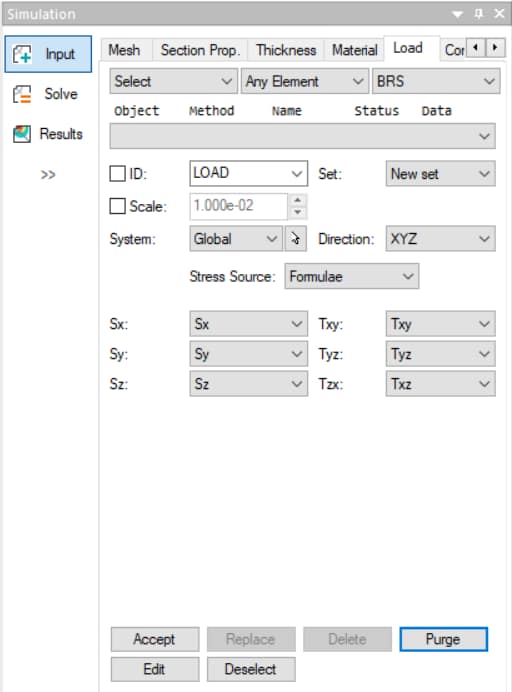
Bulk residual stress is assigned to Any Body, Any Element, All Elements or Mesh Region on the Load tab of the StressCheck Input dialog. Only one BRS load can be assigned to each element.
Imported or Mapped Solution
To assign an imported residual stress distribution solution (for example, from a forging simulation in an external tool) or to assign a StressCheck solution as a BRS load, choose Stress Source: Solution. The solution must be already associated with the elements that you wish to load.
A blank Solution dropdown indicates that there are no available solutions which are the correct type for BRS assignment. For example, the solution which represents a residual stress state may need to be converted to the correct type with the Map Solution functionality in the Bulk Residual Stress dialog under the StressCheck Edit menu.
After a Solution is chosen the Run dropdown will be populated with the available runs for that solution. Choose the desired run number for the chosen solution ID, then press Accept to create the BRS load record.
Formulae Residual Stresses
To assign a residual stress distribution which is specified by a set of formulae choose Stress Source: Formulae (Figure 6). A formula must be specified for all stress tensor components. If a component is zero, then create a formula equal to zero and assign it for that tensor component. After all six formulae are specified press Accept to create the BRS load record.
For an example of mapping cold working residual stresses to a reamed part via BRS, refer to StressCheck Tutorial: Mapping Cold Working Residual Stresses to a Reamed Part via BRS Method.
 Serving the Numerical Simulation community since 1989
