Tip: Start typing in the input box for immediate search results.Can't find what you're looking for? Submit a support request here.
Laminated Composites
Introduction
New methodology requires greater fidelity using detailed 3D ply-by-ply FEA modeling to properly assess laminated composite structural features and behaviors. This includes the analysis of bondline/interlaminar stresses and strains, thru-thickness effects, delamination assessment and other local failure mechanisms.
This article primarily focuses on the assignment of laminate orthotropic material properties to a model for use in detailed laminated composite analysis. These assignment types are as follows:
- Lamina: flat/circular lamina assignments to one or more elements/element faces
- Laminate-Stack: laminate stack assignments to element faces/edges or surfaces/curves
- Lam-Map-Edge/Lam-Map-Vol: general curvature lamina assignments to element faces/edges
As will be discussed in the following sections, assignments can be input/processed as discrete ply angles or as a sub-laminate (equivalent orthotropic “lump” based on a sequence of ply angles).
Material Property Definition
Before material properties may be assigned to individual plies (lamina), homogenized sub-laminates (lumped lamina), or laminate-stack definitions, material properties must first be defined in the Material tab, Define subtab within the Model Input pane.
The acceptable material properties for use with laminated composite analysis are Laminate-Isotropic (Lamin. Iso.) and Laminate-Orthotropic (Lamin. Ortho.). For more information on the definition of laminated material properties, please view Linear Elastic Materials.
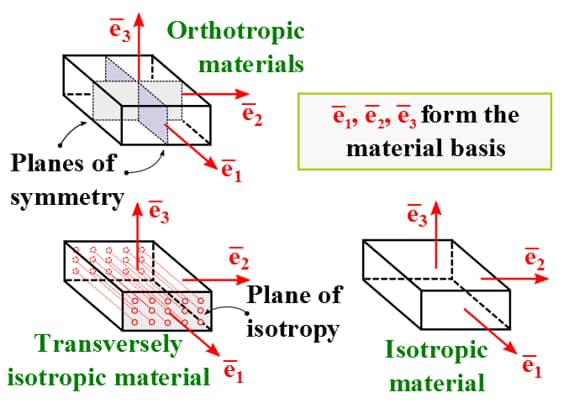
Note: Equivalent Properties for 2D Plane-Strain Analysis
When the ply angles are not contained in the standard 2D working plane (the plane-strain XY plane), the material matrix needed for the 2D analysis is extracted from the 3D material matrix. The material coefficients are entered in the material directions, and then assigned to the elements together with the ply angle information. The program then performs all necessary transformations to compute the equivalent 2D properties in the XY working plane. The appropriate 3D properties will be applied when the planar model is extruded into 3D as well.
When a set of plies needs to be combined in a single element (sub-laminate), the properties of the sub-laminate are obtained by homogenization. Again, the 3D material coefficients in the material axes of the composite are entered together with the stacking sequence of the sub-laminate, and the program computes the equivalent 2D properties in the StressCheck XY work plane for the stack.
Ply Angle (Material 1-Axis) Conventions
Ply (lamina) assignment information includes the angular orientation of each ply’s material 1-axis. The angular orientation may be defined with reference to the global system, a local Cylindrical/Cartesian coordinate system, and if the assignment type is Laminate-Stack, Lam-Map-Edge or Lam-Map-Vol, to an element edge/geometric curve.
Cartesian Reference
StressCheck makes it possible to define single-ply material properties in a Cartesian coordinate system, where the ply angle is directed at an arbitrary angle. The material axes are aligned with the local Cartesian system in such a way that a 0° ply is in the x-direction and a 90° ply is in the y-direction. With a Cartesian reference system a positive ply angle (θ) is measured as a counterclockwise rotation about the z-axis of a local coordinate system. The z-axis of the local system is aligned with the material 3-axis as shown in Figure 2.

Cylindrical Reference
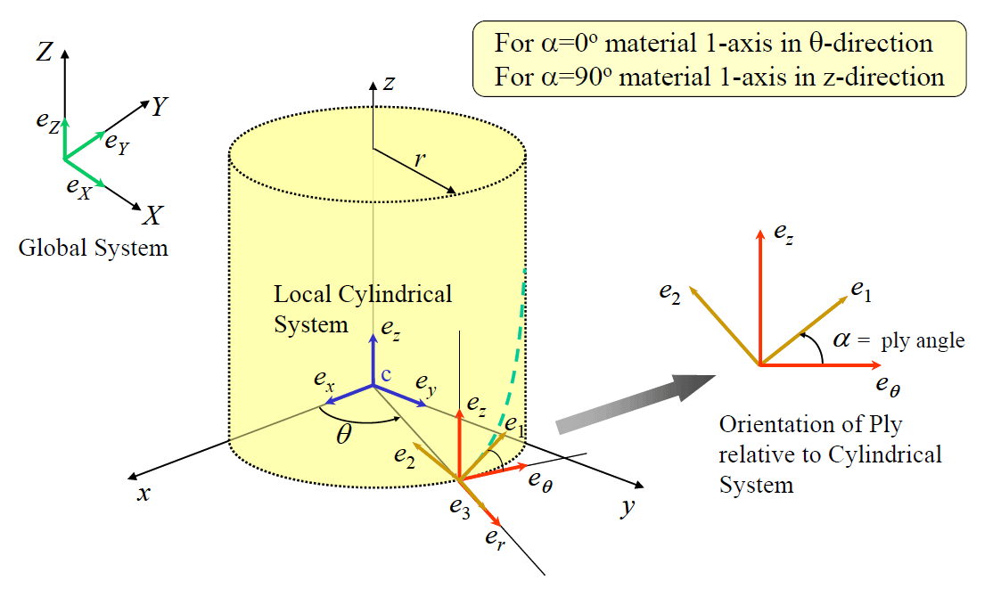
StressCheck makes it possible to define single-ply material properties in a cylindrical coordinate system, where the ply angle is directed at an arbitrary angle. The material axes are aligned with the local cylindrical system in such a way that a 0° ply is in the θ-direction and a 90° ply is in the z-direction. With a cylindrical reference system a positive ply angle (α) is measured as a counterclockwise rotation about the radial r-direction at any point on the cylindrical surface. The r-direction is aligned with the material 3-axis as shown in Figure 3.
Lamina and Laminate-Stack Overview
In assigning laminated material properties to hand-meshed elements, there are two main assignment types: Lamina and Laminate-Stack. The assignment type will be selected from the “Type:” selection drop-down on the Assign subtab of the Material tab.
- Lamina describes the selection of individual elements to create ply-by-ply material assignments. If Lamina is selected, the user may utilize the “Angle” field to supply ply orientation values. These values may be the ply angle in degrees, a user defined parameter with the value of the ply angle in degrees, or a ply sequence for sub-laminates (e.g. “0/90/0/90/0″).
- See the following section “Sub-Laminates/Homogenization” for more details.
- Laminate-Stack describes the use of StressCheck’s built-in Automatic Lamination discretization tool. If Laminate-Stack is selected, the user may assign a laminate stack definition to an element or set of elements using “Ply” (ply-by-ply discretization), “Lump” (homogenized sub-laminate) or a combination of both. The element (or elements) is then automatically divided into plies of the appropriate thickness. This procedure provides great flexibility, since various ply groups of different material properties can be automatically assembled together to represent discrete plies or sub-lamina.
- For more information on use of the Automatic Laminate Builder tool, please view Automatic Laminate Builder.
Assigning Lamina

Lamina can be assigned to hexahedral and/or pentahedral elements (or element faces) only. Select the Material tab from the input interface, select then the Define subtab, and enter the material properties as Lamin. Ortho or Lamin. Iso.
Then select the Assign subtab and proceed as follows:
- Select > Any Element OR Face/Face Surface > Selection
- ID: select a Lamin. Iso. or Lamin. Ortho. material ID from combo
- Type: Lamina
- System: select the system reference for the ply angle (material 1-axis)
- Angle: enter the value of the ply angle(s).
- The input field Angle can be the value of the ply angle in degrees, a user defined parameter with the value of the ply angle in degrees, or a ply sequence for homogenized sub-laminates.
- Hold Shift and left-click on the target elements (if Any Element) or the faces of the target elements (if Face/Face Surface).
- When the object Face Surface is used, all the faces which are slope-continuous to the one selected will be highlighted.
- Click Accept.
Assigning Laminate Stacks

Laminate-Stacks can be assigned to hexahedral and/or pentahedral elements (or element faces) only, or to geometric surfaces associated with hexahedral and/or pentahedral elements. Select the Material tab from the input interface, select then the Define subtab, and enter the material properties as Lamin. Ortho or Lamin. Iso.
Then, select the Assign subtab and follow the instructions provided in the Automatic Laminate Builder article to define, assign and process the laminate-stack(s).
Sub-Laminates/Homogenization
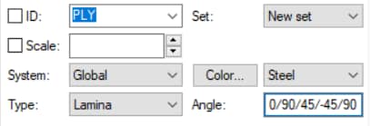
A sub-laminate is a special case of the Lamina type assignment. A sub-laminate is defined by specifying a sequence of ply angles (“/” delimited) in the “Angle:” field:
When a set of plies needs to be combined in a single layer (sub-laminate), the properties of the sub-laminate are obtained by homogenization. For more information on homogenization rules refer to: Sun, C.T. and Li, S. Three-Dimensional Effective Elastic Constants for Thick Laminates. Journal of Composite Materials, Vol. 22, pp. 629-639, 1988.
For examples of Lamina and Laminate-stack assignments for laminate orthotropic materials, refer to StressCheck Tutorial: Assigning Laminate Orthotropic Materials.
Mapped Laminates Overview
A capability is available to align laminated orthotropic material properties with the curvature of an element for both single plies and sub-laminates (Lump), given an angle orientation or stacking sequence, respectively. Two approaches are available for the definition of laminate properties with general curvature: a general mapped laminate (Lam-Map Volume), and an edge-based mapped laminate approach (Lam-Map Edge).
In both options, the principal material directions are computed based on the selection of element faces and edges from the finite element mesh:

For more background on mapped laminates, refer to Mapped Lamina Technical Brief.
Lam-Map Volume
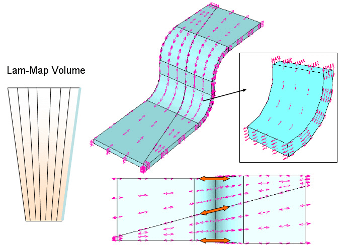
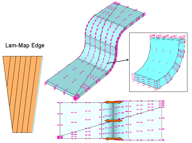
In the Lam-Map Volume option, the material 1-axis follows the natural coordinate defined by the direction of the selected edge and transitions uniformly between element faces. At any given point within an element, a unit vector is created tangent to the direction of a standard coordinate passing through the point. There are three standard coordinate directions at any given point in the element, and the one selected corresponds to the direction associated with a given edge specified by the user. For a general curvature element, this direction represents a general curve in 3D space. A second unit vector is created in the direction normal to a selected element face. An angle ply will have its angular orientation defined as a rotation about the normal direction (positive counterclockwise) and relative to the direction of the tangent vector. In other words, the material 1-axis of the orthotropic property follows the natural coordinate defined by the direction of the selected edge every-where in the element.
This option is useful when modeling injection molded parts that include cut fibers which orient themselves with the mold. This option is illustrated in Figure 8 for a single 0°-ply when the outermost edges are selected. Note that the arrows representing the material 1-axis direction do not remain parallel to the selected element edges and blend smoothly from the selected element edge to the opposite element edge.
Lam-Map Edge
In the Lam-Map Edge option, the material 1-axis follows the natural coordinate defined by the direction of the selected edge and remains parallel to the edge at all points in the domain of the element. At every point within an element a unit vector is created parallel to the tangential direction of a selected element edge. The material 1-axis will follow the natural coordinate defined by the direction of the selected edge throughout the element. A second unit vector is created in the direction normal to a selected element face, in such a way that an angle ply will have its angular orientation defined as a rotation about the second vector relative to the direction of the first vector.
This option is applicable to situations in which laminated components are created by stacking pre-preg plies. Material direction arrows throughout each element can be visualized to verify that the ply angle orientations provided conform to the problem to be analyzed. This option is illustrated in Figure 9 for a single 0°-ply when the outermost edges are selected. Note that the arrows representing the material 1-axis direction remain parallel to the selected element edges even though the opposite element edge of each element is not parallel with the selected edge.
Assigning Mapped Laminates
Similar to the Lamina and Laminate-Stack assignments, mapped laminates can be assigned to hexahedral and/or pentahedral elements (or element faces) only. Select the Material tab from the Input pane, select the Define subtab, and enter the material properties as Lamin. Iso or Lamin. Ortho.
Then select the Assign sub tab and proceed as follows:
- Select > Face/Face Surface > Selection
- ID: select a Lamin. Iso. or Lamin. Ortho. material ID from combo
- Type: Lam-Map Vol or Lam-Map Edge
- Angle: enter the value of the ply angle(s).
- The input field Angle can be the value of the ply angle in degrees, a user defined parameter with the value of the ply angle in degrees, or a ply sequence for homogenized sub-laminates.
- Hold Shift and left-click on the faces of the target elements (the normal to the face defines the axis of rotation for the ply definition), then hold Control-Shift and pick the edges on the same or opposite face of the faces selected to define the material 1-axis orientation.
- When the object Face Surface is used, all the faces which are slope-continuous to the one selected will be highlighted. When an edge is selected afterwards while holding down the Control and Shift keys, all the edges that are slope continuous to it will be highlighted.
- Click Accept.
Laminate Assignment Visualization
There are three options to facilitate visualization of laminated composite attributes after assignment. These options are accessible in the pull-down menu found next to the Display Materials icon in the main tool bar as shown in Figure 10. The options are to display the material attributes by name, with arrows, or using colors.
- If “Name” is selected, the material ID that has been assigned to each element will be display at the centroid of the element.
- If “Arrows” is chosen, the principal direction of the material fiber will be represented by arrows displayed at uniformly spaced points within each element. The density of the arrows may be controlled by the Edge Resolution setting in the View Controls interface. Note: High Edge Resolution values may cause rendering delays for exceptionally large models or models with high element counts. For such cases, it is recommended to set Edge Resolution: 2.
- If “Color” is selected, each element will be displayed using a color from a user-defined color table, according to the angle of the principal material direction relative to the global coordinate system or assigned local coordinate system. The laminate color table may be defined in the Assign tab of the Material Input Class interface.
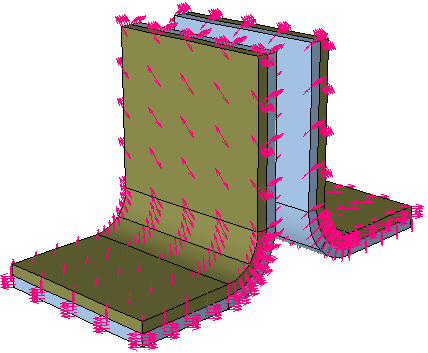
In the example shown in Figure 11, “Arrows” is selected and the material 1-direction arrows are displayed over the elements.

 Serving the Numerical Simulation community since 1989
