Tip: Start typing in the input box for immediate search results.Can't find what you're looking for? Submit a support request here.
Advanced StressCheck Automation: Model Setup & Analysis
Introduction
In the StressCheck Automation Fundamentals article, we focused on the basics of automating StressCheck Handbook models for parameter updates, solutions and simple extractions via scripting. In the following article, we will learn to perform more advanced StressCheck automation tasks such as:
- Adding new model parameters
- Creating 3D solid bodies
- Adjustment of model view/orientation settings
- Defining named sets for storage of object lists
- Automatic meshing of parts
- Material property definition and assignment
- Assignment of loads and constraints to named sets
- Adjustment of model object displays
- Defining and executing linear solution settings
- Defining and executing contour plots and other extraction settings
- Advanced DataTable queries
- Saving project files
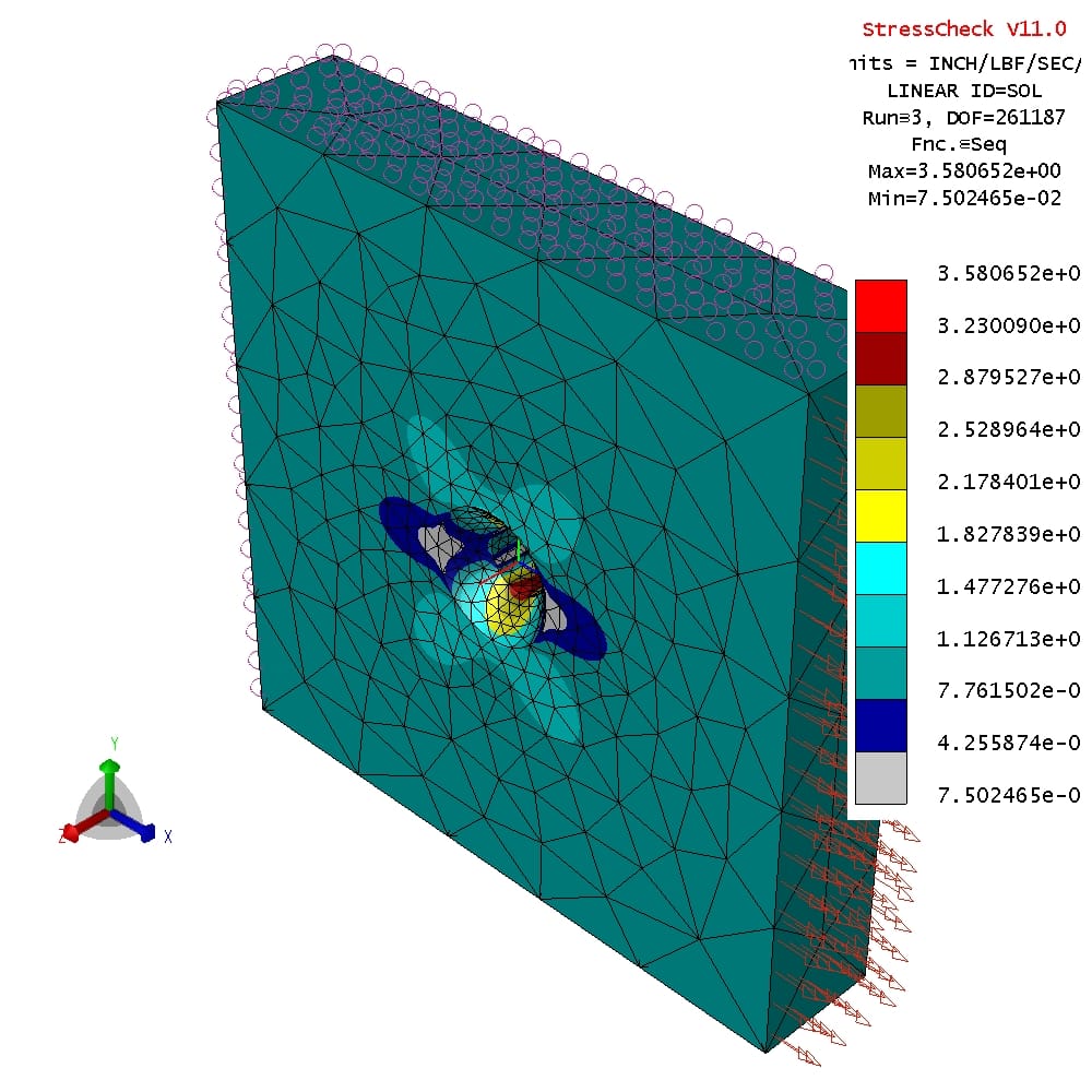
To demonstrate the VBA and Python code for the above advanced scripting tasks, we will perform a stress concentration factor analysis on a 3D plate with a countersink bore. The model setup, solution and results were produced entirely from scratch via automation scripting!
Python Script Prerequisites
In addition to importing the required win32com.client module at the beginning of our Python script, we must also import two other modules (os and pythoncom) to ensure the Python-COM-StressCheck bridge is seamlessly connected. Therefore, it is best to include the following at the top of your Python script:
#import libraries/modules
import os
import win32com.client as win32
from win32com.client import VARIANT
import pythoncom
from pythoncom import VT_ARRAY
from pythoncom import VT_R8
from pythoncom import VT_I4
Note that the line “import win32com.client as win32” simply maps the win32com.client module to win32 to save characters. Details on how the os and pythoncom modules enable advanced scripting will be discussed further on in this article, when passing arrays of different data types via COM (i.e. VARIANT structures) and saving project files to a working directory.
Adding New Model Parameters
After starting a new StressCheck session (see StressCheck Automation Fundamentals to review the requirements), we will create a parameter for the plate length (“Lplate”). This can be done by accessing the Info property of the StressCheck Application’s Document level, and then digging one more level to access the Parameters collection; note that a collection is a type that contains a set of related objects.
Again, StressCheck’s Application object follows a typical object hierarchy, with lower hierarchic levels accessed by adding a “.” between objects/properties/methods. Therefore, to access the Parameters collection we would write Application.Document.Info.Parameters. We can then use the Add method of Parameters to add our parameter “Lplate” and give it a value of 5 units, a requirement of “>0”, a sorting order of “a1”, and a parameter type of “General” (pcGeneral). The Add method arguments and syntax are as follows:
Function Add(parameter_name As String, descript As String, curval, [DataCheck], [SortKey As String = " "], [Category As ParameterCategoryType = pcGeneral]) As Parameter
Note that arguments listed between the [] characters are considered optional, with the defaults provided after the “=”.
Note also that the Category argument takes a ParameterCategoryType enumeration, with a default enumerator of pcGeneral. An enumeration is a collection of Long/Integer data types that have fixed numeric values. Enumerations provide a way of categorizing (or grouping) your symbolic constants into a defined structure. StressCheck uses many different enumerations to set the properties of objects, as we will be demonstrating throughout this documentation.
Excel VBA
In VBA, it is very simple to view the arguments of the Add method of Parameters by clicking View > Object Browser while in the VBA Editor, changing <All Libraries> in the top left drop down to StressCheck, and searching for Parameters. Then, click on the Add method in the “Members of ‘Parameters’ list:
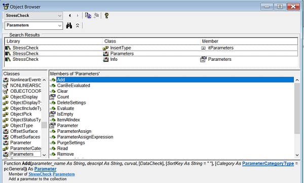
Using the above argument list, we will set:
- parameter_name = “Lplate”
- descript = “Plate Length”
- curval = 5
- DataCheck = “>0” (optional)
- SortKey = “a1” (optional)
The VBA code would then be:
SCApp.Document.Info.Parameters.Add "Lplate", "Plate Length", 5, ">0", "a1"
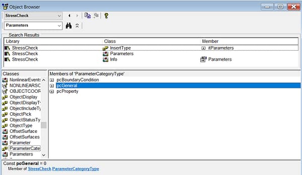
Note that if we click on the ParameterCategoryType enumeration hyperlink, and then the pcGeneral enumerator, we see that pcGeneral is set to 0 (default):
Python
In the absence of Excel VBA, we can investigate the arguments of the Parameters.Add method by opening the COM Programming Help (in StressCheck, use Help > COM Programming Help) and searching for Parameters:
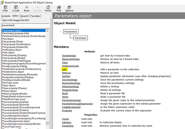
Clicking on “Add” will result in the argument list from top to bottom:
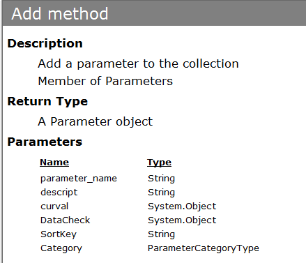
The Python code would then be:
scapp.Document.Info.Parameters.Add(
    parameter_name='Lplate',
    descript='Plate Length',
    curval=5,
    DataCheck='>0',
    SortKey='a1',
    Category=0) #pcGeneral
Note that in Python we supplied the Long/Integer value of the ParameterCategoryType enumeration, which in this case is 0 (pcGeneral); we will be following this convention throughout our Python code for other enumerations.
Creating 3D Solid Bodies
Now that we have a parameter defined, next we will create a parametric 3D solid countersink plate using two local systems, a box, a cylinder, a cone and Boolean subtraction operations. To do so, we will need to access the StressCheck.Document.Model level, where we will then find the Cylinders, Boxes, Cones and Bodies collections.
Each of these collections includes the Add (user-specified object number) and AddAuto (next available object number) methods; the Add and AddAuto methods will return a new object of the same type as the collection. For this example, we will be using the AddAuto method so that we do not have to specify the next object number for each particular collection.
When creating solid bodies such as boxes, cylinders and/or cones, we will need to specify a local system number in the Add/AddAuto arguments. Therefore, we will need to generate local system objects before attempting to add a new solid body. Local systems can be added with a variety of methods, such as at a global location (AddAutoGlobal), attached to a local system (AddAutoLocal) and more:
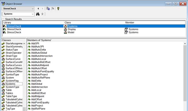
For this example, we will be creating two systems at (0, 0, 0) and (0, 0, 0.75) using the AddAutoGlobal method. The AddAutoGlobal method arguments and syntax are as follows:
Function AddAutoGlobal(Type As SystemType, x, y, z, [rot_xyz]) As System
Note that rot_xyz is an optional array of three rotations (Rot-X, Rot-Y, Rot-Z). For this example, we do not need to provide this array as the systems will be aligned with the global axis. And for the system Type argument, we must provide a SystemType enumeration. In this case, we will use the stCartesian enumerator, which is set to 0 and is the default.
We can now create a solid box, cone and cylinder using the system numbers. Again, we will use the AddAuto method such that the object number does not have to be specified by the user. First, we will add a solid box associated with system 1 of Width = 5, Length = ‘Lplate” and Depth = 1. The syntax and arguments for adding a Box to the Boxes collection via the AddAuto method are:
Function AddAuto(system_num As Long, Width, Height, Depth) As Box
Then, we will add a solid cylinder associated with system 1 of Radius = 0.25 and Height = 0.75. The syntax and arguments for adding a Cylinder to the Cylinders collection via the AddAuto method are:
Function AddAuto(system_num As Long, Radius, Height, is_solid As Boolean, [p1_minmax], [p2_minmax]) As Cylinder
Note the is_solid argument determines if the resulting cylinder is solid body (True) or a sheet body (False). If is_solid is False, the optional arguments p1_minmax and p2_minmax may be used to create cylindrical surface patches.
Next, we will add a solid cone associated with system 2 of Radius1 = 0.25, Radius2 = 0.5 and Height = 0.25. The syntax and arguments for adding a Cone to the Cones collection via the AddAuto method are:
Function AddAuto(system_num As Long, Radius1, Radius2, Height, is_solid As Boolean, [p1_minmax], [p2_minmax]) As Cone
As with the cylinder, we can specify if the cone is a solid or surface, and if it is a surface we can specify a conical patch.
Finally, we will Boolean-Subtract the cylinder and cone (tools) from the box (target) to create a countersink hole. To do so, we will use the AddAutoBooleanSubtract method of the Bodies collection. The body_target value is 1 (box body number), and the body_tools list values are 2 (cylinder body number) and 3 (cone body number). The syntax and arguments for adding a new result Body to the Bodies collection via the AddAutoBooleanSubtract method are:
Function AddAutoBooleanSubtract(body_target As Long, body_tools() As Long) As Body
Note that the body_tools() argument will expect an array of integers.
Excel VBA
The Excel VBA code for creating the countersink plate body would be:
SCApp.Document.Model.Systems.AddAutoGlobal stCartesian, 0, 0, 0 'Create a local system (system label is 1)
SCApp.Document.Model.Systems.AddAutoGlobal stCartesian, 0, 0, 0.75 'Create a coordinate system for the cone base location
SCApp.Document.Model.Boxes.AddAuto 1, 5, "Lplate", 1 'Create a box at the system we just created
SCApp.Document.Model.Cylinders.AddAuto 1, 0.25, 0.75, True 'Create a cylinder using the same system than the box
SCApp.Document.Model.Cones.AddAuto 2, 0.25, 0.5, 0.25, True 'Create a cone. The “True” at the end indicates the cone will be a solid
Dim tools(1) As Long 'The operation needs an array with the numbers identifying the solid bodies
tools(0) = 2
tools(1) = 3
'Subtract the cone (body 2) and cylinder (body 3) form the box performing a boolean operation
SCApp.Document.Model.Bodies.AddAutoBooleanSubtract 1, tools
Note that if we wanted a cylindrical system as the Type, we would use stCylindrical instead of stCartesian.
Python
The Python code for creating the countersink plate body would be:
scapp.Document.Model.Systems.AddAutoGlobal(
    Type=0, #stCartesian
    x=0,
    y=0,
    z=0)
scapp.Document.Model.Systems.AddAutoGlobal(
    Type=0, #stCartesian
    x=0,
    y=0,
    z=0.75)
scapp.Document.Model.Boxes.AddAuto(
    system_num=1,
    Width=5,
    Height='Lplate',
    Depth=1)
scapp.Document.Model.Cylinders.AddAuto(
    system_num=1,
    Radius=0.25,
    Height=0.75,
    is_solid=True)
scapp.Document.Model.Cones.AddAuto(
    system_num=2,
    Radius1=0.25,
    Radius2=0.5,
    Height=0.25,
    is_solid=True)
tools = [2,3] #define list of tool body numbers
scapp.Document.Model.Bodies.AddAutoBooleanSubtract(
    body_target=1,
    body_tools=tools)
Adjusting the Model View/Orientation
Once the 3D solid body is available, we can adjust its view/orientation through the StressCheck.Document.Model.Display level. Within the Display properties of the Model object, we can adjust a wide variety of settings, such as the display of object types (e.g. elements, nodes, surfaces, etc.), the model orientation (Front, Left, Isometric, Center Model, etc.), change geometry/element display resolution(s), display load/constraint attributes, create custom view settings, and more.
For this example, we will focus on the Orientation property of Display. The Orientation property takes a ViewType enumeration as its argument:
Property Orientation As ViewType
The ViewType enumerators are listed as follows:
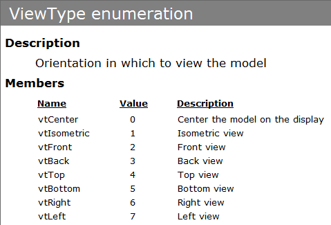
We would like to center the model in the display, and then set the orientation of the model view to be Isometric. To do so, we will take advantage of the vtCenter (value 0) and vtIsometric (value 1) enumerators.
Excel VBA
The VBA code to center the model and set the view to Isometric would be:
SCApp.Document.Model.Display.Orientation = vtCenter
SCApp.Document.Model.Display.Orientation = vtIsometric
Python
The Python code to center the model and set the view to Isometric would be:
scapp.Document.Model.Display.Orientation = 0 #vtCenter
scapp.Document.Model.Display.Orientation = 1 #vtIsometric
Defining Named Sets for Storage of Object Lists
In order to generate an automesh for the solid countersink plate body, and to make subsequent assignments of loads/constraints to the geometry, we will need to define sets.
Sets can be of a specific object type (e.g. bodies, surfaces, elements, etc.) or of any object type, and will store lists of the associated object number(s). For this example, we will need to define a body set for the automesh generation, a surface/boundary set for traction load assignment, two surface/boundary sets for symmetry constraint assignment, and a point set for a nodal constraint assignment.
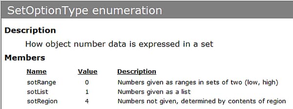
To add a set, we will need to access StressCheck.Document.Model.Sets and use the Add and AddRegionSet methods. First, we will add a body set (Type = stBody or value 10) with set_name “BODY” which will contain the last body number generated in the model (i.e. the result of the Boolean-Subtract operation) in the obj_list array. The set option type (otype) in this case will be sotList (value 1) as we will be providing a list containing a single body number. We will then use this body set to generate an automesh of tetrahedra.
The syntax and arguments for adding a Set to the Sets collection via the Add method are as follows:
Function Add(set_name As String, Type As SetObjectType, otype As SetOptionType, obj_list, [edgeface_nums]) As Set
Note that the Type argument takes a SetObjectType enumeration, while the otype argument takes a SetOptionType enumeration. These are listed as follows:
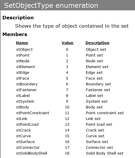
Next, we will add surface sets (set_names “TRACTION”, “SYM1”, and “SYM2” of object type stBoundary or value 6) and a point set (set_name “Z” of object type stPoint or value 1) to define our boundary condition object lists. Note that for AddRegionSet, the Add method’s Type and otype arguments have been combined into a single argument otype; otype will expect a SetObjectType enumeration.
Since we don’t know the surface/boundary numbers in advance, AddRegionSet will allow us to specify a box pick location (xyz) and tolerance (values), and will return the “found” object number(s) within the box pick (rtype = srtBox or value 0, the only enumerator in the SetRegionType enumeration).
The syntax and arguments for adding a Set to the Sets collection via the AddRegionSet method are:
Function AddRegionSet(set_name As String, otype As SetObjectType, rtype As SetRegionType, xyz, values, [sys_num As Long]) As Set
Optionally, the location/orientation of the box pick may be controlled by providing a local system number (sys_num); otherwise the global system (0) will be specified.
Excel VBA
The VBA code to add a body set, three surface/boundary sets, and a point set would be:
'Get the last body number using .LastNumber property of Bodies
Dim body(0) As Long
body(0) = SCApp.Document.Model.Bodies.LastNumber
'Add a body set called “BODY” that uses the result body
SCApp.Document.Model.Sets.Add "BODY", stBody, sotList, body

'Define load and constraint sets
'Need to define “Sets” using “AddRegionSet” method. This method requires  creating a "pick" box that will enclose part of the object(s) we will select for the assignment
Dim gcoords(2) As Variant 'box location
Dim box(2) As Variant 'box tolerance
gcoords(0) = 2.5 'Global coordinate on the x-direction
gcoords(1) = 0     'Global coordinate on the y-direction
gcoords(2) = 0.5 'Global coordinate on the z-direction
box(0) = box(1) = box(2) = 0.01 'Pick tolerance

'Create surface/boundary set for Traction load
SCApp.Document.Model.Sets.AddRegionSet "Traction", stBoundary, srtBox, gcoords, box

'Create surface/boundary sets for Symmetry constraints
gcoords(0) = 0
gcoords(1) = "Lplate/2"
SCApp.Document.Model.Sets.AddRegionSet "Sym1", stBoundary, srtBox, gcoords, box
gcoords(0) = -2.5
gcoords(1) = 0
SCApp.Document.Model.Sets.AddRegionSet "Sym2", stBoundary, srtBox, gcoords, box

'Create point set for nodal constraint
gcoords(0) = 2.5
gcoords(1) = "Lplate/2"
gcoords(2) = 0
SCApp.Document.Model.Sets.AddRegionSet "Z", stPoint, srtBox, gcoords, box
Python
The Python code to add a body set, three surface/boundary sets, and a point set would be:
#Get the last body number using .LastNumber property of Bodies
body = scapp.Document.Model.Bodies.LastNumber
#Define body set for automeshing
scapp.Document.Model.Sets.Add(
    set_name='BODY',
    Type=10, #stBody
    otype=1, #sotList
    obj_list=body)
#Define load and constraint sets
gcoords = [2.5,0,0.5]
box = [0.01,0.01,0.01]
scapp.Document.Model.Sets.AddRegionSet(
    set_name='Traction',
    otype=6, #stBoundary
    rtype=0, #srtBox
    xyz=gcoords,
    values=box)
gcoords[0] = 0
gcoords[1] = 'Lplate/2'
scapp.Document.Model.Sets.AddRegionSet(
    set_name='Sym1',
    otype=6, #stBoundary
    rtype=0, #srtBox
    xyz=gcoords,
    values=box)
gcoords[0] = -2.5
gcoords[1] = 0
scapp.Document.Model.Sets.AddRegionSet(
    set_name='Sym2',
    otype=6, #stBoundary
    rtype=0, #srtBox
    xyz=gcoords,
    values=box)
gcoords[0] = 2.5
gcoords[1] = 'Lplate/2'
gcoords[2] = 0
scapp.Document.Model.Sets.AddRegionSet(
    set_name='Z',
    otype=1, #stPoint
    rtype=0, #srtBox
    xyz=gcoords,
    values=box)
Generating Automeshes
Now that we have a body set containing the number of our result body, we pass the body set (“BODY”) to the MeshSim automesher to generate an 3D automesh of tetrahedral elements. In order to automesh the body, we will need to access Application.Document.Model.Automeshes and use the AddAutoMeshSimGlobal method to add a global MeshSim automesh record. Then, we can use the Automesh method of Model to generate the automesh.
The only required argument to the AddAutoMeshSimGlobal method is the body set name (SetName=”BODY”). The syntax and arguments to add a new MeshSim global automesh record to the Automeshes collection via the AddAutoMeshSimGlobal method are:
Function AddAutoMeshSimGlobal(SetName As String, [amtype As AutomeshType = meshTetra], [mesh_active As Boolean = True], [ratio_active As Boolean = False], [dh_active As Boolean = False], [minlen_active As Boolean = False], [isopar_active As Boolean = True], [trans_active As Boolean = False], [angle_active As Boolean = False], [ratio_str = 0.75], [dh_str = 0.114], [minlen_str = 0.015], [trans_str = 0.05], [angle_str = 5]) As Automesh
Note that since all other arguments are optional, we can specify which MeshSim input defaults will be overridden. For this example, we would like to use Curvature D/H (dh_str) = 0.05. To do so, we will need to ensure the dh_active argument is set to True.
Once we have added the MeshSim global automesh record, we can generate the automesh using the Model’s Automesh method and optionally providing Type = aeAutomesh or value 0. The arguments and syntax for the Automesh method are:
Function Automesh([Type As AutomeshExecute = aeAutomesh]) As Long
The AutomeshExecute enumeration provides two enumerators: aeAutomesh (default) and aeHRefine. Note that if we generated the mesh by hand and wanted to refine the hand mesh, we can use Type = aeHRefine or value 1 to process any h-Discretizations.
Excel VBA
The VBA code to add the global MeshSim automesh record and generate the automesh is:
'Add a global mesh record using BODY, set D/H to 0.05 to refine around the countersink
SCApp.Document.Model.Automeshes.AddAutoMeshSimGlobal "BODY", meshTetra, True, False, True, False, True, False, False, , 0.05
SCApp.Document.Model.Automesh aeAutomesh 'Execute automesh
Note that in VBA we can simply omit an optional argument with “, ,” if we do not wish to override its value. For example, we used “, ,” to ensure the default Ratio value (ratio_str) did not get updated.
Python
The Python code to add the global MeshSim automesh record and generate the automesh is:
#Generate automesh
scapp.Document.Model.Automeshes.AddAutoMeshSimGlobal(
    SetName='BODY',
    amtype=3, #meshTetra
    mesh_active=True,
    ratio_active=False,
    dh_active=True,
    minlen_active=False,
    isopar_active=True,
    trans_active=False,
    angle_active=False,
    ratio_str=0.75,
    dh_str=0.05)
scapp.Document.Model.Automesh(
    Type=0) #aeAutomesh
In Python, we must provide the default value for ratio_str (i.e. 0.75) as we cannot use “, ,” to omit an argument.
Defining and Assigning Linear Elastic Material Properties
Now that we have generated our 3D automesh, we can define linear elastic material properties and assign the material properties to all elements within the mesh.
First, we will define a new MATERIALDEF structure to store the linear elastic material property data (e.g. material coefficients, material name, description, etc.); a structure is a concatenation of one or more members of various data types. Then, we will add the new material definition (“ALUMINUM”) via the populated MATERIALDEF structure. Finally, we will assign the “ALUMINUM” material definition to all elements.
The MATERIALDEF structure (i.e. user-defined type, or UDT) we will populate is as follows:
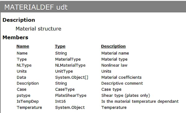
To populate a member of the MATERIALDEF structure, we will write the name of the variable (e.g. linearmat or matdef) followed by a “.” and the member name. Not all members of a MATERIALDEF structure need to be populated as the defaults will be sufficient.
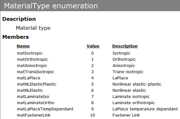
For this example, we will focus on populating the Name (“ALUMINUM”), the Type (matIsotropic or value 0), the Description (“Material”) and the Data (array of material coefficients). Note that the Type member expects a MaterialType enumeration:
The Data array is 23 elements in length, and the Data array indices should be specified from 0 to 22 (per Excel VBA and Python convention). Note that the 0th index of the Data array represents the elastic modulus (Em), and the 3rd index of the Data array represents Poisson’s ratio (nu). For this example, we will set the elastic modulus to 1e7 psi and the Poisson’s ratio to 0.3.
Once the MATERIALDEF structure is populated, we can access Application.Document.Model.Materials and use the AddRecord method to add the MATERIALDEF structure’s data to the Materials collection. The arguments and syntax for adding a new material definition to the Materials collection via the AddRecord method are:
Function AddRecord(struc As MATERIALDEF) As Material
Then, we can assign the material definition to all elements in the model by accessing Application.Document.Model.MaterialAssignments and using the Add method. The required arguments are the material_name (“ALUMINUM”), the set_name (can specify “” since a set name is not required if using All Elements), the assignment type assign (use atAll or value 1 to assign to All Elements in the mesh), and the system number sys_num = 0 (the global system).
The arguments and syntax for adding a new material assignment record to the MaterialAssignments collection via the Add method are:
Function Add(material_name As String, set_name As String, assign As Assignment, sys_num As Long, [Type As MaterialAssignType = matHomogeneous], [color_name As String = "Steel"], [Angle]) As MaterialAssignment
Excel VBA
The VBA code to define and assign a linear elastic material to all elements is:
'Define aluminum material using a “MATERIALDEF” structure:
Dim linearmat As StressCheck.MATERIALDEF
Dim coeffs(22) As Variant
coeffs(0) = 10000000# 'coeffs(0) in the case of isotropic materials is the elastic modulus
coeffs(3) = 0.3 'coeffs(3) in the case of isotropic materials is the Poisson’s ratio
With linearmat
    .Data = coeffs
    .Name = "Aluminum"
    .Type = matIsotropic
    .Description = "Material"
End With
SCApp.Document.Model.Materials.AddRecord linearmat 'Add/create complete material record
SCApp.Document.Model.MaterialAssignments.Add "Aluminum", "", atAll, 0 'Assign aluminum material to all elements
Note that in VBA we needed to declare a variable linearmat as type MATERIALDEF. We then used a “With/End With” statement to populate the members of the MATERIALDEF structure.
Python
The Python code to define and assign a linear elastic material to all elements is:
#Define and assign material properties
matdef = win32.Record('MATERIALDEF', scapp)
coeffs = [0]*22
coeffs[0] = 1e7
coeffs[3] = 0.3
matdef.Data = coeffs
matdef.Name = 'Aluminum'
matdef.Type = 0
matdef.Description = 'Material'
scapp.Document.Model.Materials.AddRecord(matdef) #add material definition
#Assign aluminum material to all elements
scapp.Document.Model.MaterialAssignments.Add(
    'Aluminum',
    '', #no set name needed
    1, #atAll
    0) #global system
Note that to create a new MATERIALDEF structure to be populated (matdef), we needed to use the Record method of the win32 (i.e. win32com.client) module and provide as arguments the structure type (MATERIALDEF) and the StressCheck application instance (scapp).
Material Data Array Standard
The MATERIALDEF Data() array coefficients and their respective positions in the array are as follows:
Linear Material Coefficients
Elasticity – Isotropic
| E | 0 |
| V | 3 |
| ALPHA | 6 |
| THICKNESS | 19 (For Laminated plate) |
| SHEAR | 20 |
| DENSITY | 21 |
Elasticity – Orthotropic
| E11 | 0 |
| E22 | 1 |
| E33 | 2 |
| V12 | 3 |
| V23 | 4 |
| V31 | 5 |
| G12 | 6 |
| G23 | 7 |
| G31 | 8 |
| A11 | 9 |
| A22 | 10 |
| A33 | 11 |
| DENSITY | 21 |
| ANGLE | 22 |
| THICKNESS | 19 (For laminated plate) |
Elasticity – Anisotropic
| A1 | 0 |
| A2 | 1 |
| A3 | 2 |
| A4 | 3 |
| A5 | 4 |
| A6 | 5 |
| A7 | 6 |
| A8 | 7 |
| A9 | 8 |
| A10 | 9 |
| A11 | 10 |
| A12 | 11 |
| A13 | 12 |
| A14 | 13 |
| A15 | 14 |
| A16 | 15 |
| A17 | 16 |
| A18 | 17 |
| A19 | 18 |
| A20 | 19 |
| A21 | 20 |
| DENSITY | 21 |
Elasticity – Transverse Isotropic
| E11 | 0 |
| E22 | 1 |
| V12 | 3 |
| V23 | 4 |
| G12 | 6 |
| A11 | 9 |
| A22 | 10 |
| DENSITY | 21 |
Elasticity – Stiffness
| STIFFNESS | 0 |
Elasticity – Laminate Isotropic
Same as Isotropic.
Elasticity – Laminate Orthotropic
Same as Orthotropic.
Heat Transfer
| KXX | 0 |
| KXY | 1 |
| KYY | 2 |
| KXZ | 3 |
| KZZ | 4 |
| KYZ | 5 |
| Q | 6 |
| TEMPERATURE | 7 |
Nonlinear Material Coefficients
| E1 | 0 |
| E2 | 1 (S70E if R-O, Et if Bilinear/5-parameter |
| V | 3 |
| ALPHA | 6 |
| A1 | 7 (n if R-O, Sy if E-P/Bilinear/5-parameter) |
| A2 | 8 (Eps-2 if 5-parameter) |
| A3 | 9 (S2 if 5-parameter) |
Assigning Loads to Named Sets
We are now ready to assign boundary conditions (i.e. loads and constraints) to our surface/boundary and point sets. We will start by assigning a traction load to our “TRACTION” boundary set.
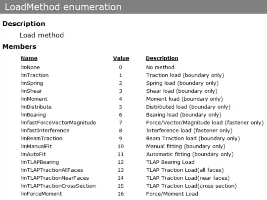
In order to add a new boundary load (e.g. traction, bearing, force/moment, TLAP, spring displacement) to a named boundary/surface set in the model, we can access Application.Document.Model.Loads and use the AddBoundaryLoad method. For a load case with load_name “LOAD”, we wish to add a normal traction (lmtype = lmTraction or value 1, and Direction = dtNormalTangent or value 1) of 1.0 psi to the boundary/surface in set_name “TRACTION” using the global system sys_num = 0. Since we are assigning to a set, we will use atype = atSet or value 2.
The arguments and syntax for adding a new boundary load to the Loads collection via the AddBoundaryLoad method are as follows:
Function AddBoundaryLoad(load_name As String, set_name As String, lmtype As LoadMethod, Direction As Direction, atype As Assignment, sys_num As Long, Data, types, [fmla_setname], [case_id As String], [load_boundary_force_option As LoadBoundaryForceOption = lbfDefault], [tlap_option As TLAPOption = tloDefault], [load_bearing_correction_option As LoadBearingCorrectionOption = lbcCorrected], [Update As Boolean = True]) As Load
Note that the lmtype argument takes a LoadMethod enumeration, while Direction takes a Direction enumeration. The members of these enumerations are listed as follows:
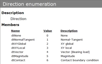
Next, we will prepare our Data and associated types for assignment of the normal traction load. Data expects a System.Object/Variant array, while types expects a corresponding LoadValueType enumeration/Integer array of the same length as the Data array. The LoadValueType enumeration has the following members:
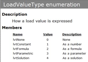
In general, a 3D traction with Direction = dtXYGlobal or value 2 expects three directional traction components (X, Y, Z) which may be specified as a constant (lvtConstant or value 1), parameter (lvtParametric or value 3), formula (lvtFormula or value 2), or disabled (lvtNone or value 0). Below is the StressCheck GUI for Select > Any Surface > Traction in the case of Direction: XYZ, with X: 1 psi, Y: 2 psi, and Z: 3 psi:
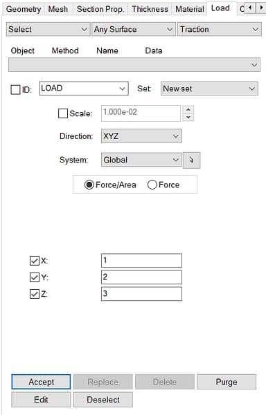
So, the Data array in the above case may contain a list of up to three (3) System.Object/Variant values representing the XYZ traction components: (1, 2, 3), and the types array would contain up to three (3) LoadValueType/Integer values representing the input data: (lvtConstant, lvtConstant, lvtConstant) or in integer form (1, 1, 1). In this way, we can represent any mixture of LoadValueType names/values (e.g. constants, parameters, formulae) when preparing our Data array for the AddBoundaryLoad method.
Since we are using Direction = dtNormalTangent in this case, the Data array only requires one (1) System.Object/Variant value (normal traction component). And, as we wish to assign a constant normal traction load of 1.0 psi, the types array only requires one (1) LoadValueType/Integer value (lvtConstant or value 1).
Additional options are available to specify if the traction is in units of force/area or force, or to specify information during a TLAP Traction or TLAP Bearing assignment:
- case_id: if LoadMethod is lmTLAP**** then a point load definition Case ID may be specified.
- load_boundary_force_option: the user may specify a LoadBoundaryForceOption enumeration in units of force/area via the lbfDefault or value 0, or in units of force via lbfForce or value 1.
- tlap_option: if LoadMethod is lmTLAPBearing, then a TLAPOption enumeration may be specified as tloDefault (Default, or value 0) or tloIMO (Ignore Moments/Offsets, or value 1).
- load_bearing_correction_option: if the LoadMethod is lmTLAPBearing or Bearing, then a LoadBearingCorrectionOption enumeration may be specified as lbcCorrected (Default, or value 1) or lbcUncorrected (Legacy, value 0).
Note: non-homogeneous constraint assignments such as general and spring coefficient also use Data/types arrays, except that a ConstraintValueType enumeration array would be specified.
Excel VBA
The VBA code to assign a normal traction load to a surface/boundary set is:
'Assign unit traction load normal to the “Traction” surface
Dim ldata(0) As Variant, ltype(0) As LoadValueType 'only need normal component
ldata(0) = 1#
ltype(0) = lvtConstant

SCApp.Document.Model.Loads.AddBoundaryLoad "LOAD", "Traction", lmTraction, dtNormalTangent, atSet, 0, ldata, ltype
Note that in VBA the Data array (ldata) is declared as a Variant data type, and our types array (ltype) is a declared as a LoadValueType data type. In Python, we must use a pywin32 module (pythoncom) to map Python object types to/from COM VARIANT structures.
Python
Recall that at the beginning of our Python script, we imported specific modules to help us communicate with StressCheck’s API via COM VARIANT structures:
from win32com.client import VARIANT
import pythoncom
from pythoncom import VT_ARRAY
from pythoncom import VT_R8
from pythoncom import VT_I4
The win32com.client VARIANT object, as well as pythoncom’s VT_ARRAY (list/array ), VT_R8 (float), and VT_I4 (32-bit integer), provide a means to map information properly between Python object types and COM VARIANT structures. From Tim Golden’s win32com documentation:
win32com attempts to provide a seamless COM interface and hide many COM implementation details, including the use of COM VARIANT structures. This means that in most cases, you just call a COM object using normal Python objects as parameters and get back normal Python objects as results.
However, in some cases this doesn’t work very well, particularly when using “dynamic” (aka late-bound) objects, or when using “makepy” (aka early-bound) objects which only declare a parameter is a VARIANT.
The
win32com.client.VARIANTobject is designed to overcome these problems… The VARIANT object lives inwin32com.client. The constructor takes 2 parameters – the ‘variant type’ and the value. The ‘variant type’ is an integer and can be one or more of thepythoncom.VT_*values, possibly or’d together.For example, to create a VARIANT object which defines a byref array of 32bit integers, you could use:
v = VARIANT(pythoncom.VT_BYREF | pythoncom.VT_ARRAY | pythoncom.VT_I4, [1,2,3,4])
This variable can then be used wherever a COM VARIANT is expected.
Using the above mappings/translations, and after importing pythoncom and its VT_ARRAY, VT_R8 and VT_I4 modules, the Python code to assign a normal traction load with a Data array of (1.0,) and a types array of (lvtConstant=1,) to a surface/boundary set is:
#Assign traction load
lvals = (1.0,) #Normal=1.0
ltypes = (1,) #lvtConstant
scapp.Document.Model.Loads.AddBoundaryLoad(
    load_name='LOAD',
    set_name='Traction',
    lmtype=1, #lmTraction
    Direction=1, #dtNormalTangent
    atype=2, #atSet
    sys_num=0, #global system
    Data=VARIANT(VT_ARRAY | VT_R8,lvals), #pass byref array of floats as a VARIANT
    types=VARIANT(VT_ARRAY | VT_I4,ltypes) #pass byref array of integers as a VARIANT
    )
Assigning Constraints to Named Sets
Next, we will assign symmetry constraints to our “SYM1” and “SYM2” boundary sets, and a nodal constraint in the global-Z direction to our “Z” point set.
In order to add a new boundary constraint to a named boundary/surface set in the model, we can access Application.Document.Model.Constraints and use the AddBoundaryConstraint method (if a general, spring coefficient or contact constraint) or AddHomogeneousBoundaryConstraint method (if a symmetry, built-in, or anti-symmetry constraint). Because we are assigning a symmetry constraint, we will use the AddHomogeneousBoundaryConstraint method.
For a constraint case with const_name “CONST”, we wish to add a symmetry constraint (Method = hcmSymmetry or value 5) to the boundary/surface in set_name “SYM1” and “SYM2”.
The arguments and syntax for adding a new boundary constraint to the Constraints collection via the AddHomogeneousBoundaryConstraint method are as follows:
Function AddHomogeneousBoundaryConstraint(const_name As String, set_name As String, Method As HomogeneousConstraintMethod, [Update As Boolean = True]) As Constraint
Note that the Method argument takes a HomogeneousConstraintMethod enumeration. The members of this enumeration are listed as follows:
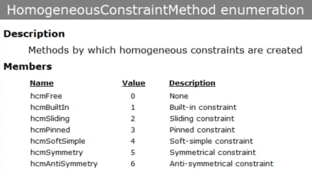
In order to add a new nodal constraint to a named point set in the model, we can access Application.Document.Model.Constraints and use the AddNodeConstraint method. For a constraint case with const_name “CONST”, we wish to add a nodal constraint of Z=0 to a point object (obj = coPoint or value 1) in set_name “Z”. We will use Direction: XYZ (Direction = dtXYGlobal or value 2) in the global system sys_num = 0.
The arguments and syntax for adding a new nodal constraint to the Constraints collection via the AddNodeConstraint method are as follows:
Function AddNodeConstraint(const_name As String, obj As ConstraintObject, obj_num As Long, Direction As Direction, sys_num As Long, Data, types, [is_extruded As Boolean = False], [fmla_setname], [Update As Boolean = True]) As Constraint
Note that the obj argument takes a ConstraintObject enumeration, and the Direction argument takes a Direction enumeration. The only members are coPoint (value 1) and coNode (value 2), while the Direction members are listed in Figure 13.
Next, we will prepare our Data and associated types for assignment of the point constraint in the global Z-direction. As mentioned in the previous section, Data expects a System.Object/Variant array, while types expects a corresponding ConstraintValueType enumeration/Integer array of the same length as the Data array. The ConstraintValueType enumeration has the following members:
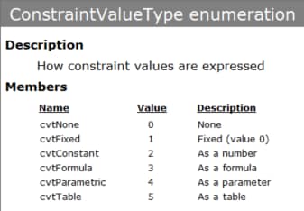
In general, a 3D nodal constraint expects three directional displacement components (X, Y, Z) which are typically specified as fixed (cvtFixed or value 1) or disabled (cvtNone or value 0). Below is the StressCheck GUI for Select > Point > Node in which the X and Z directions are fixed (Rx, Ry, Rz are for beam elements only):
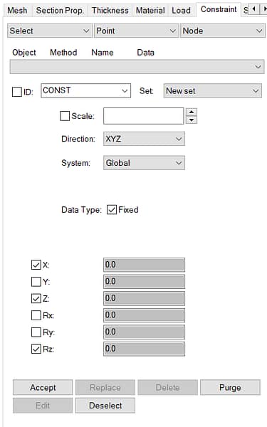
So, the Data array in the above case may contain a list of up to three (3) System.Object/Variant values representing the nodal displacement components: (0, 0, 0), and the types array would contain up to three (3) ConstraintValueType/Integer values representing the input data: (cvtFixed, cvtNone, cvtFixed) or in integer form (1, 0, 1).
In our case, we simply wish to fix the Z-direction, so the types array would have the form (cvtNone, cvtNone, cvtFixed) or in integer form (0, 0, 1).
Excel VBA
The VBA code for assigning symmetry constraints to two surface/boundary sets and a nodal constraint in the global Z-direction to a point number in a point set is:
'Assign symmetry constraints on the “Sym1” and “Sym2” surfaces
SCApp.Document.Model.Constraints.AddHomogeneousBoundaryConstraint "CONST", "Sym1", hcmSymmetry
SCApp.Document.Model.Constraints.AddHomogeneousBoundaryConstraint "CONST", "Sym2", hcmSymmetry

'Assign point constraint on “Z” point
Dim ptnum() As Long
ptnum = SCApp.Document.Model.Sets.Set("Z").ObjectList 'Get the point number in the set
Dim cdata(2) As Variant, ctype(2) As ConstraintValueType
'We only need to enforce the Z direction, other directions are "None" by default
cdata(2) = 0#
ctype(2) = cvtFixed
SCApp.Document.Model.Constraints.AddNodeConstraint "CONST", coPoint, ptnum(0), dtXYGlobal, 0, cdata, ctype
Python
The Python code for assigning symmetry constraints to two surface/boundary sets and a nodal constraint in the global Z-direction to a point number in a point set is:
#Assign symmetry constraints
scapp.Document.Model.Constraints.AddHomogeneousBoundaryConstraint(
    const_name='CONST',
    set_name='Sym1',
    Method=5)
scapp.Document.Model.Constraints.AddHomogeneousBoundaryConstraint(
    const_name='CONST',
    set_name='Sym2',
    Method=5)
#Assign nodal constraint in Z-direction
ptnum = scapp.Document.Model.Sets.Set("Z").ObjectList
cvals = (0,0,0)
ctypes = (0,0,1)
scapp.Document.Model.Constraints.AddNodeConstraint(
    const_name='CONST',
    obj=1, #coPoint
    obj_num=ptnum[0], #Point number found in set "Z"
    Direction=2, #dtXYGlobal
    sys_num=0, #global system
    Data=VARIANT(VT_ARRAY | VT_R8,cvals), #pass byref array of floats as a VARIANT
    types=VARIANT(VT_ARRAY | VT_I4,ctypes) #pass byref array of integers as a VARIANT
    )
Note that similar to the Python code for adding a new boundary load, we used the VARIANT, VT_ARRAY, VT_R8 and VT_I4 modules to pass the data to StressCheck via COM.
Setting Model Object and Attribute Displays
If we wish to display certain objects/attributes in the model, which is very helpful when automating screen captures and fringe plots, we can again access the Application.Document.Model.Display level and enable/disable specific object types and/or load/constraint attributes.
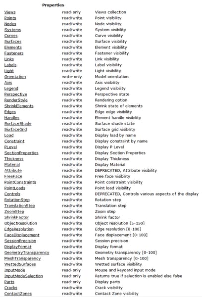
For example, we can disable the display of Points, Nodes, Surfaces and Curves, and enable the display of Elements. We can also enable the display of the load attributes for “LOAD” and the constraint attributes for “CONST”.
The properties available in Display are:
Excel VBA
The VBA code to display Elements and “LOAD”/”CONST” is:
'Change display of objects to show elements only
SCApp.Document.Model.Display.Points = False
SCApp.Document.Model.Display.Nodes = False
SCApp.Document.Model.Display.Surfaces = False
SCApp.Document.Model.Display.Curves = False
SCApp.Document.Model.Display.Elements = True
'Display load/constraint attributes
SCApp.Document.Model.Display.Load = "LOAD"
SCApp.Document.Model.Display.Constraint = "CONST"
Python
The Python code to display Elements and “LOAD”/”CONST” is:
#Show elements only
scapp.Document.Model.Display.Points = False
scapp.Document.Model.Display.Nodes = False
scapp.Document.Model.Display.Surfaces = False
scapp.Document.Model.Display.Curves = False
scapp.Document.Model.Display.Elements = True
#Display load and constraint attributes
scapp.Document.Model.Display.Load = 'LOAD'
scapp.Document.Model.Display.Constraint = 'CONST'
Defining and Executing a Linear Solution
We have now defined all of our model inputs, and are ready to solve a linear p-extension! We must first define a solution ID to pair the load and constraint together. To do so, we access Application.Document.Model.SolutionIDs and use the Add method to add a new solution ID.
For a solution_name “SOL”, we wish to pair constraint_name “CONST” with load_name “LOAD” and set it to active (Status = ssActive or value 1). We will solve all objects in the model (Type = stAllObjects or value 0).
The arguments and syntax for adding a new solution ID to the SolutionIDs collection via the Add method are:
Function Add(solution_name As String, constraint_name As String, load_name As String, Status As SolutionStatus, [Type As SolutionIDType = stAllObjects]) As SolutionID
Now that we have an active solution ID “SOL”, we can solve this solution ID via a linear p-extension. To set up a linear solution, we need to define a new LINEARSOLUTION structure (similar to how we defined the MATERIALDEF structure). The LINEARSOLUTION structure will contain the Name of our solution ID (“SOL”), the starting p-level (PLevel) and the limiting p-level (PLimit).
The LINEARSOLUTION structure (i.e. user-defined type, or UDT) members are as follows:
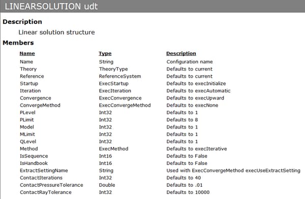
For this example, we will use PLevel = 2 and PLimit = 4. All other members will use the LINEARSOLUTION structure defaults.
Once the LINEARSOLUTION structure is populated, we can access Application.Document.Solutions and use the AddLinear method to add the LINEARSOLUTION structure’s data to the Solutions collection. The arguments and syntax for adding a new linear solution to the Solutions collection via the AddLinear method are:
Function AddLinear(sol_struc As LINEARSOLUTION) As Solution
We will then execute the linear solution setting by using the xSolve method of Application.Document, and providing the Name property of the LINEARSOLUTION structure as solution_name. The arguments and syntax for executing a solution via the xSolve method are:
Function xSolve(solution_name As String) As DataTable
Note that it is possible to return a DataTable object after the solution executes. The information in the DataTable will depend on the solution settings and solver type.
Excel VBA
The VBA code to define a solution ID, add a linear solution setting, and execute the solution is:
'Create the solution record and run the linear solution
SCApp.Document.Model.SolutionIDs.Add "SOL", "CONST", "LOAD", ssActive
'Define a new LINEARSOLUTION structure
Dim linsol As StressCheck.LINEARSOLUTION
With linsol
    .Name = "LinearSol"
    .PLevel = 2
    .PLimit = 4
End With
'Add LINEARSOLUTION structure to solutions collection
SCApp.Document.Solutions.AddLinear linsol
'Execute the linear solution setting
SCApp.Document.xSolve "LinearSol"
Python
The Python code to define a solution ID, add a linear solution setting, and execute the solution is:
#Create solution ID record
scapp.Document.Model.SolutionIDs.Add(
    solution_name='SOL',
    constraint_name='CONST',
    load_name='LOAD',
    Status=1 #ssActive
    )
#Define linear solution setting
linsol = win32.Record('LINEARSOLUTION', scapp)
linsol.Name='LinearSol'
linsol.PLevel=2
linsol.PLimit=4
scapp.Document.Solutions.AddLinear(linsol)
#Solve the linear solution
scapp.Document.xSolve('LinearSol')
Defining and Executing Plots and Other Results Extractions
Once a solution is available, we can define any number of results plots and extractions (error, min/max, points, resultant, and fracture). All results are computed dynamically, meaning there is no pre-computed output. This allows us great flexibility in scripting automation of results post-processing.
First, we will define a contour plot for the von Mises stress (Seq). To do so, we will need to define a new PLOTEXTRACTION structure. The PLOTEXTRACTION structure will contain the Name of the fringe plot (“SeqPlot”), the function we wish to plot (EFunction = efSeq or value 30), instructions to autoscale the contour plot (IsAutoscaleContour = True), instructions to activate fringe contours (IsFringePlot = True), the number of midsides/plot resolution used (Midsides = 6), instructions to plot All Elements (Object = plotAll or value 1), the solution ID to be plotted (SolutionID = “SOL”), the solution run number to be plotted (Run = 3), and the model view to be plotted (ViewName = “Current”).
The PLOTEXTRACTION structure (i.e. user-defined type, or UDT) members are as follows:
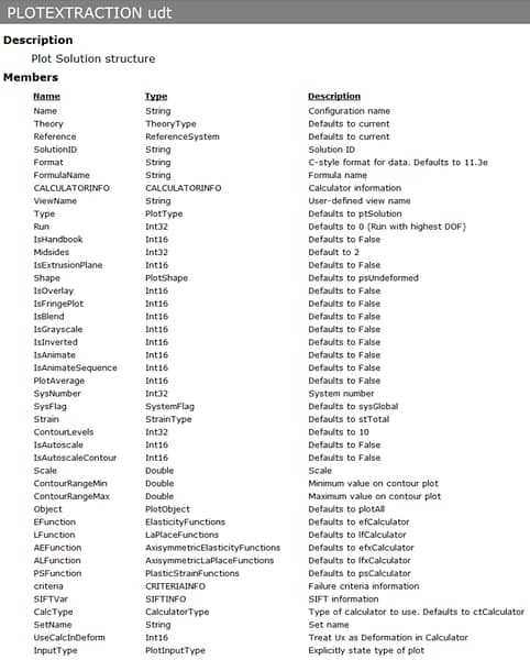
As can be seen from the members in Figure 21, numerous other options are available to customize the plot, such as contour ranges, contour intervals, system number, deformed shape, display format and more.
Once the PLOTEXTRACTION structure is populated, we can access Application.Document.Plots and use the Add method to add the PLOTEXTRACTION structure’s data to the Plots collection. The arguments and syntax for adding a new plot to the Plots collection via the Add method are:
Function Add(plot_struc As PLOTEXTRACTION) As Plot
We will then execute the plot setting by using the xPlot method of Application.Document, and providing the Name property of the PLOTEXTRACTION structure as plot_name. Additionally, an image file (e.g. JPEG, PNG) may be captured and saved to any path by providing a filename. The arguments and syntax for executing a solution via the xSolve method are:
Function xPlot(plot_name As String, [filename], [Width As Double = 5], [Height As Double = 5], [Units As UnitType = utUS]) As PlotResults
Note that it is possible to return a PlotResults object after the plot executes. The PlotResults object contains such information as the computed function minimum/maximum, max/min deformation, and plot scale.
Next, we wish to extract the maximum von Mises stress (max Seq) for all elements in the mesh, and return the max Seq and relative error to a DataTable for further data processing/reporting. To do so, we will need to define a new MINMAXEXTRACTION structure. The MINMAXEXTRACTION structure will contain the Name of the min/max extraction (“MaxSeq”), the function we wish to extract (EFunction = efSeq or value 30), instructions to extract only the maximum function value (Maximum = True), instructions to create a graph object (CreateGraph = True) the method used for the extraction (Method = extGrid or value 5), the number of midsides/search resolution used (Midsides = 10), instructions to extract over All Elements (Object = mmoAllElements or value 42), the solution ID to be extracted (SolutionID = “SOL”), the minimum solution run number to be extracted (RunMin = 1), and the maximum solution run number to be extracted (RunMax = 3).
The MINMAXEXTRACTION structure (i.e. user-defined type, or UDT) members are as follows:
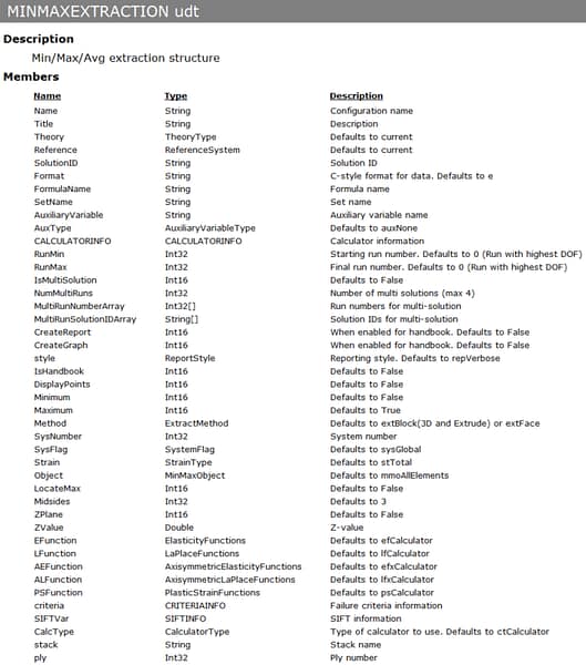
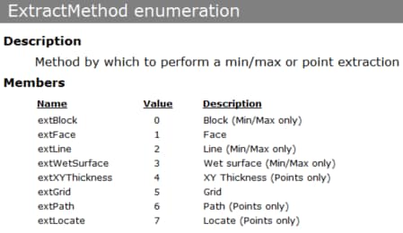
As can be seen from the members in Figure 21, numerous other options are available to customize the plot, such as contour ranges, contour intervals, system number, deformed shape, display format and more. Note that the Method argument expects a ExtractMethod enumeration, and the Object argument expects a MinMaxObject enumeration. The ExtractMethod enumeration members are:
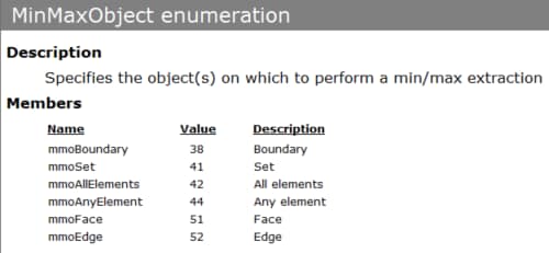
And the MinMaxObject enumeration members are:
Once the MINMAXEXTRACTION structure is populated, we can access Application.Document.Extractions and use the AddMinMaxExtraction method to add the MINMAXEXTRACTION structure’s data to the Extractions collection. The arguments and syntax for adding a new min/max extraction to the Extractions collection via the AddMinMaxExtraction method are:
Function AddMinMaxExtraction(minmax_struc As MINMAXEXTRACTION) As Extraction
We will then execute the min/max extraction setting by using the xExtractData method of Application.Document, and providing the Name property of the MINMAXEXTRACTION structure as extraction_name. The arguments and syntax for executing an extraction via the xExtractData method are:
Function xExtractData(extraction_name As String) As DataTable
The return of xExtractData will be a DataTable object. In the next section, we will perform advanced queries on this DataTable object.
Excel VBA
The VBA code to define and execute a fringe plot and min/max extraction of the von Mises stress (Seq) is:
'Define plot and min/max extractions and execute settings
'Define fringe contour plot setting for von Mises stress (Seq)
Dim fringeplot As StressCheck.PLOTEXTRACTION
With fringeplot
    .EFunction = efSeq
    .IsAutoscaleContour = True
    .IsFringePlot = True
    .Midsides = 6
    .Name = "SeqPlot"
    .Object = plotAll
    .Run = 3
    .ViewName = "Current"
    .SolutionID = "SOL"
End With
'Add plot setting to Plots collection
SCApp.Document.Plots.Add fringeplot
'Execute the contour (fringe) plot setting and output a JPG file to the Excel path
SCApp.Document.xPlot "SeqPlot", ThisWorkbook.Path & "\fringeplotvba.jpg", 10, 10, utNone
'Define Min/Max extraction setting for max von Mises stress (Seq)
Dim maxseq As StressCheck.MINMAXEXTRACTION
With maxseq
    .CreateGraph = True
    .EFunction = efSeq
    .Maximum = True
    .Method = extGrid
    .Midsides = 10
    .Name = "MaxSeq"
    .Object = mmoAllElements
    .RunMin = 1
    .RunMax = 3
    .SolutionID = "SOL"
End With
'Add min/max extraction setting to Extractions collection
SCApp.Document.Extractions.AddMinMaxExtraction maxseq
'Execute the min/max extraction setting, and return the extraction to a DataTable object “scdt”
Dim scdt As StressCheck.DataTable
Set scdt = SCApp.Document.xExtractData("MaxSeq")
Python
The Python code to define and execute a fringe plot and min/max extraction of the von Mises stress (Seq) is:
#Define a contour plot setting
fringeplot = win32.Record('PLOTEXTRACTION', scapp)
fringeplot.EFunction = 30 #efSeq
fringeplot.IsAutoscaleContour = True
fringeplot.IsFringePlot = True
fringeplot.Midsides = 6
fringeplot.Name = 'SeqPlot'
fringeplot.Object = 1 #plotAll
fringeplot.Run = 3
fringeplot.ViewName = 'Current'
fringeplot.SolutionID = 'SOL'
#Add plot setting to Plots collection
scapp.Document.Plots.Add(fringeplot)
#Plot von Mises stress for the model and save JPG capture to script path
scapp.Document.xPlot('SeqPlot',os.path.abspath(os.path.dirname(__file__)) + '\fringeplotpy.jpg',10,10,0)
#Define a min/max extraction setting
maxseq = win32.Record('MINMAXEXTRACTION', scapp)
maxseq.CreateGraph = True
maxseq.EFunction = 30 #efSeq
maxseq.Maximum = True
maxseq.Method = 5 #extGrid
maxseq.Midsides = 10
maxseq.Name = 'MaxSeq'
maxseq.Object = 42 #mmoAllElements
maxseq.RunMin = 1
maxseq.RunMax = 3
maxseq.SolutionID = 'SOL'
#Add min/max setting to Extractions collection
scapp.Document.Extractions.AddMinMaxExtraction(maxseq)
#Extract maximum Seq for the model and return the extraction to a DataTable object scdt
scdt = scapp.Document.xExtractData('MaxSeq')
Advanced DataTable Queries
Accessing specific information in a DataTable object, such as pulling stress values from the DataTable’s Data property, was discussed briefly in StressCheck Automation Fundamentals. In this section, we will perform more advanced DataTable queries via the DataTable’s Columns, Rows and ResultsRows collections. In addition to these collections, the DataTable object has the following members:
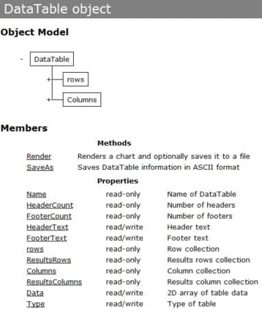
Note that the DataTable object is organized in row/column format (i.e. a MxN grid). First, we will walk through our DataTable object’s Columns collection to find the Column with Name “Seq_max”. Once found, we will query the max Seq value from that Column’s Cells collection using the Cell corresponding to the last Row number in the DataTable’s Rows collection; the last Row number in a Rows collection can be found via its Count property.
Then, we will pull the first Row from the DataTable’s ResultsRows collection and query the max Seq’s relative error by pulling the first Cell value in that Row’s Cells collection. Finally, we will report the max Seq and relative error information to the user. In Excel VBA, we will report this information via a message box (MsgBox), while in Python we will report this information to the Python console via print().
Excel VBA
The VBA code for querying the max Seq value and associated relative error and displaying the values in a VBA message box is:
'Pull max von Mises stress from the “scdt” datatable
Dim maxseqval As Double, error As Double
Dim maxrow As Double, col As StressCheck.Column
maxrow = scdt.Rows.Count - 1 'Subtract 1 from total row count since VBA uses zero based arrays
For Each col In scdt.Columns 'We need to search for the column with name “Seq_max”
    If col.Name = "Seq_max" Then
        maxseqval = col.Cells.Cell(maxrow).Value
    End If
Next col
'Pull error from the “scdt” datatable
Dim row As StressCheck.row
Set row = scdt.ResultsRows.row(1) 'The error is in the first row
error = row.Cells.Cell(1).Value
'Display maximum von Mises strain and relative error in a message box
MsgBox "Maximum von Mises Stress = " & maxseqval & ", with a relative error of " & error & "%", vbOKCancel, "Maximum von Mises Stress"
Python
The Python code for querying the max Seq value and associated relative error and printing the values to the Python console is:
#Get max Seq value from the datatable
maxrow = scdt.rows.Count - 1
for col in scdt.Columns:
    if(col.Name=='Seq_max'):
        maxseqval = col.Cells.Cell(maxrow).Value
#Get max Seq estimated relative error from the datatable
errorrow = scdt.ResultsRows.Row(1)
errorval = errorrow.Cells.Cell(1).Value
#Print the max Seq value and estimated relative error to the console
print("Maximum von Mises stress is %f and the associated relative error is %f percent" % (maxseqval, errorval))
Saving a StressCheck Project File
We can save a new StressCheck project file (SCP) at any time by using the SaveAs method of Application.Document. We simply must provide the filename and the path as one string value (file). The arguments and syntax for saving a new StressCheck project file via the SaveAs method are:
Sub SaveAs(file As String)
For example, “C:\Temp\model.scp” would write a new project file model.scp to C:\Temp. For simplicity, we will save the project file to the same directory as our Excel VBA worksheet and Python script.
Note: we must remember to close StressCheck once we are finished with our automation tasks. As described in StressCheck Automation Fundamentals, to ensure that the StressCheck.Application object is destroyed, we must use the Close method of Application.
Excel VBA
The VBA code for saving a new project file “AutomeshPlateSolved.scp” to the same path as the current Excel macro (.xlsm) file and then closing StressCheck is:
'Save the project file
SCApp.Document.SaveAs ThisWorkbook.Path & "\AutomeshPlateSolved.scp"
'Close StressCheck
SCApp.Close 'Close the application
Set SCApp = Nothing 'Clear out the SCApp
Note that we used the built-in Excel function ThisWorkbook.Path to return the absolute path to the directory of the running Excel VBA file.
Python
The Python code for saving a new project file “AutomeshPlateSolved.scp” to the same path as the current Python script (.py) file and then closing StressCheck is:
#Save the project file
scapp.Document.SaveAs(os.path.abspath(os.path.dirname(__file__)) + '\\AutoMeshPlateSolved.scp')
#Close StressCheck
scapp.Close()
Note that we used the os (i.e. operating system) module’s path.abspath and passed the __file__ variable to os.path.dirname method to return the absolute path to the current directory of the running Python script.
Executing the Script
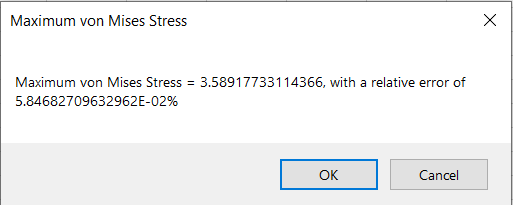
We can now execute the Excel VBA and/or Python code using the Run/Play commands described in StressCheck Automation Fundamentals. The expected results are:
- Max Seq (psi) = 3.589177
- Relative error (%) = 0.058468%.
Excel VBA
After completion of the Excel VBA macro, the following message box is displayed:
Python
After completion of the Python script, the following is printed to the Python console:

Try It Yourself
The complete VBA code for the above example is as follows:
Sub Main()

    'We don't want to be disturbed by Excel prompts and alert messages while the macro is running;
    'any time a message requires a response, Microsoft Excel chooses the default response.
    Application.DisplayAlerts = False

    'Declare a StressCheck Application Object (SCApp)
    Dim SCApp As StressCheck.Application

    'Make SCApp a new StressCheck Application
    Set SCApp = New StressCheck.Application

    'Show StressCheck GUI
    SCApp.Show True

    'Define parameters using the “Info” property of SCApp.Document
    SCApp.Document.Info.Parameters.Add "Lplate", "Plate Length", 5, ">0", "a1", pcGeneral

    'Geometry creation
    'Create a box object
    SCApp.Document.Model.Systems.AddAutoGlobal stCartesian, 0, 0, 0 'Create a local system (system label is 1)
    SCApp.Document.Model.Systems.AddAutoGlobal stCartesian, 0, 0, 0.75 'Create a coordinate system for the cone base location
    SCApp.Document.Model.Boxes.AddAuto 1, 5, "Lplate", 1 'Create a box at the system we just created
    SCApp.Document.Model.Cylinders.AddAuto 1, 0.25, 0.75, True 'Create a cylinder using the same system than the box
    SCApp.Document.Model.Cones.AddAuto 2, 0.25, 0.5, 0.25, True 'Create a cone. The “True” at the end indicates the cone will be a solid

    Dim tools(1) As Long 'The operation needs an array with the numbers identifying the solid bodies
    tools(0) = 2
    tools(1) = 3
    'Subtract the cone (body 2) and cylinder (body 3) form the box performing a boolean operation
    SCApp.Document.Model.Bodies.AddAutoBooleanSubtract 1, tools

    'Set the display orientation
    SCApp.Document.Model.Display.Orientation = vtCenter
    SCApp.Document.Model.Display.Orientation = vtIsometric

    'Get the last body number using .LastNumber property of Bodies
    Dim body(0) As Long
    body(0) = SCApp.Document.Model.Bodies.LastNumber
    'Add a body set called “BODY” that uses the result body
    SCApp.Document.Model.Sets.Add "BODY", stBody, sotList, body

    'Define load and constraint sets
    'Need to define “Sets” using “AddRegionSet” method. This method requires  creating a "pick" box that will enclose part of the object(s) we will select for the assignment
    Dim gcoords(2) As Variant 'box location
    Dim box(2) As Variant 'box tolerance
    gcoords(0) = 2.5 'Global coordinate on the x-direction
    gcoords(1) = 0     'Global coordinate on the y-direction
    gcoords(2) = 0.5 'Global coordinate on the z-direction
    box(0) = box(1) = box(2) = 0.01 'Pick tolerance

    'Create surface/boundary set for Traction load
    SCApp.Document.Model.Sets.AddRegionSet "Traction", stBoundary, srtBox, gcoords, box

    'Create surface/boundary sets for Symmetry constraints
    gcoords(0) = 0
    gcoords(1) = "Lplate/2"
    SCApp.Document.Model.Sets.AddRegionSet "Sym1", stBoundary, srtBox, gcoords, box
    gcoords(0) = -2.5
    gcoords(1) = 0
    SCApp.Document.Model.Sets.AddRegionSet "Sym2", stBoundary, srtBox, gcoords, box

    'Create point set for nodal constraint
    gcoords(0) = 2.5
    gcoords(1) = "Lplate/2"
    gcoords(2) = 0
    SCApp.Document.Model.Sets.AddRegionSet "Z", stPoint, srtBox, gcoords, box

    'Add a global mesh record using BODY, set D/H to 0.05 to refine around the countersink
    SCApp.Document.Model.Automeshes.AddAutoMeshSimGlobal "BODY", meshTetra, True, False, True, False, True, False, False, , 0.05
    SCApp.Document.Model.Automesh aeAutomesh 'Execute automesh

    'Define and assign a material record
    'Define aluminum material using a “MATERIALDEF” structure:
    Dim linearmat As StressCheck.MATERIALDEF
    Dim coeffs(22) As Variant
    coeffs(0) = 10000000# 'coeffs(0) in the case of isotropic materials is the elastic modulus
    coeffs(3) = 0.3 'coeffs(3) in the case of isotropic materials is the Poisson’s ratio

    With linearmat
        .Data = coeffs
        .Name = "Aluminum"
        .Type = matIsotropic
        .Description = "Material"
    End With

    SCApp.Document.Model.Materials.AddRecord linearmat 'Add/create complete material record
    SCApp.Document.Model.MaterialAssignments.Add "Aluminum", "", atAll, 0 'Assign aluminum material to all elements

    'Assign Boundary conditions
    'Assign unit traction load normal to the “Traction” surface
    Dim ldata(0) As Variant, ltype(0) As LoadValueType
    ldata(0) = 1#
    ltype(0) = lvtConstant

    SCApp.Document.Model.Loads.AddBoundaryLoad "LOAD", "Traction", lmTraction, dtNormalTangent, atSet, 0, ldata, ltype

    'Assign symmetry constraints on the “Sym1” and “Sym2” surfaces
    SCApp.Document.Model.Constraints.AddHomogeneousBoundaryConstraint "CONST", "Sym1", hcmSymmetry
    SCApp.Document.Model.Constraints.AddHomogeneousBoundaryConstraint "CONST", "Sym2", hcmSymmetry

    'Assign point constraint on “Z” point
    Dim ptnum() As Long
    ptnum = SCApp.Document.Model.Sets.Set("Z").ObjectList 'Get the point number in the set

    Dim cdata(2) As Variant, ctype(2) As ConstraintValueType
    cdata(2) = 0#
    ctype(2) = cvtFixed

    SCApp.Document.Model.Constraints.AddNodeConstraint "CONST", coPoint, ptnum(0), dtXYGlobal, 0, cdata, ctype

    'Change display of objects to show elements only
    SCApp.Document.Model.Display.Points = False
    SCApp.Document.Model.Display.Nodes = False
    SCApp.Document.Model.Display.Surfaces = False
    SCApp.Document.Model.Display.Curves = False
    SCApp.Document.Model.Display.Elements = True
    'Display load/constraint attributes
    SCApp.Document.Model.Display.Load = "LOAD"
    SCApp.Document.Model.Display.Constraint = "CONST"

    'Create the solution record and run the linear solution
    SCApp.Document.Model.SolutionIDs.Add "SOL", "CONST", "LOAD", ssActive

    'Define linear solution setting
    Dim linsol As StressCheck.LINEARSOLUTION

    With linsol
        .Name = "LinearSol"
        .PLevel = 2
        .PLimit = 4
    End With

    SCApp.Document.Solutions.AddLinear linsol

    'Exceute the linear solution setting
    SCApp.Document.xSolve "LinearSol"

    'Define extractions and execute settings
    'Define contour (fringe) plot for equivalent (von Mises) stresses (Seq)
    Dim fringeplot As StressCheck.PLOTEXTRACTION

    With fringeplot
        .EFunction = efSeq
        .IsAutoscaleContour = True
        .IsFringePlot = True
        .Midsides = 6
        .Name = "SeqPlot"
        .Object = plotAll
        .Run = 3
        .ViewName = "Current"
        .SolutionID = "SOL"
    End With

    SCApp.Document.Plots.Add fringeplot

    'Execute the contour (fringe) plot setting
    SCApp.Document.xPlot "SeqPlot", ThisWorkbook.Path & "\fringeplotvba.jpg", 10, 10, utNone

    'Define Min/Max extraction setting for equivalent stress
    Dim maxseq As StressCheck.MINMAXEXTRACTION

    With maxseq
        .CreateGraph = True
        .EFunction = efSeq
        .Maximum = True
        .Method = extGrid
        .Midsides = 10
        .Name = "MaxSeq"
        .Object = mmoAllElements
        .RunMin = 1
        .RunMax = 3
        .SolutionID = "SOL"
    End With

    SCApp.Document.Extractions.AddMinMaxExtraction maxseq

    'Execute the min/max extraction setting, and return the extraction to a datatable object “scdt”
    Dim scdt As StressCheck.DataTable
    Set scdt = SCApp.Document.xExtractData("MaxSeq")

    'Pull max von Mises stress from the “scdt” datatable
    Dim maxseqval As Double, error As Double
    Dim maxrow As Double, col As StressCheck.Column

    maxrow = scdt.Rows.Count - 1 'Subtract 1 from total row count since VBA uses zero based arrays

    For Each col In scdt.Columns 'We need to search for the column with name “Seq_max”
        If col.Name = "Seq_max" Then
            maxseqval = col.Cells.Cell(maxrow).Value
        End If
    Next col

    'Pull error from the “scdt” datatable
    Dim row As StressCheck.row
    Set row = scdt.ResultsRows.row(1) 'The error is in the first row
    error = row.Cells.Cell(1).Value

    'Display maximum von Mises strain and relative error in a message box
    MsgBox "Maximum von Mises Stress = " & maxseqval & ", with a relative error of " & error & "%", vbOKCancel, "Maximum von Mises Stress"

    'Save the project file
    SCApp.Document.SaveAs ThisWorkbook.Path & "\AutomeshPlateSolved.scp"

    'Close StressCheck
    SCApp.Close 'Close the application
    Set SCApp = Nothing 'Clear out the SCApp

End Sub
The complete Python code for the above example is as follows:
#import libraries/modules
import os
import win32com.client as win32
from win32com.client import VARIANT
import pythoncom
from pythoncom import VT_ARRAY
from pythoncom import VT_R8
from pythoncom import VT_I4
#Open a new SC
scapp = win32.gencache.EnsureDispatch('StressCheck.Application')
scapp.Show(True)
#Solid modeling
scapp.Document.Info.Parameters.Add(
    parameter_name='Lplate',
    descript='Plate Length',
    curval=5,
    DataCheck='>0',
    SortKey='a1',
    Category=0) #pcGeneral
scapp.Document.Model.Systems.AddAutoGlobal(
    Type=0, #stCartesian
    x=0,
    y=0,
    z=0)
scapp.Document.Model.Systems.AddAutoGlobal(
    Type=0, #stCartesian
    x=0,
    y=0,
    z=0.75)
scapp.Document.Model.Boxes.AddAuto(
    system_num=1,
    Width=5,
    Height='Lplate',
    Depth=1)
scapp.Document.Model.Cylinders.AddAuto(
    system_num=1,
    Radius=0.25,
    Height=0.75,
    is_solid=True)
scapp.Document.Model.Cones.AddAuto(
    system_num=2,
    Radius1=0.25,
    Radius2=0.5,
    Height=0.25,
    is_solid=True)
tools = [2,3]
scapp.Document.Model.Bodies.AddAutoBooleanSubtract(
    body_target=1,
    body_tools=tools)
#Set display orientation
scapp.Document.Model.Display.Orientation = 0
scapp.Document.Model.Display.Orientation = 1
#Define body set for automeshing
body = scapp.Document.Model.Bodies.LastNumber
scapp.Document.Model.Sets.Add(
    set_name='BODY',
    Type=10, #stBody
    otype=1, #sotList
    obj_list=body)
#Define load and constraint sets
gcoords = [2.5,0,0.5]
box = [0.01,0.01,0.01]
scapp.Document.Model.Sets.AddRegionSet(
    set_name='Traction',
    otype=6, #stBoundary
    rtype=0, #srtBox
    xyz=gcoords,
    values=box)
gcoords[0] = 0
gcoords[1] = 'Lplate/2'
scapp.Document.Model.Sets.AddRegionSet(
    set_name='Sym1',
    otype=6, #stBoundary
    rtype=0, #srtBox
    xyz=gcoords,
    values=box)
gcoords[0] = -2.5
gcoords[1] = 0
scapp.Document.Model.Sets.AddRegionSet(
    set_name='Sym2',
    otype=6, #stBoundary
    rtype=0, #srtBox
    xyz=gcoords,
    values=box)
gcoords[0] = 2.5
gcoords[1] = 'Lplate/2'
gcoords[2] = 0
scapp.Document.Model.Sets.AddRegionSet(
    set_name='Z',
    otype=1, #stPoint
    rtype=0, #srtBox
    xyz=gcoords,
    values=box)
#Generate automesh
scapp.Document.Model.Automeshes.AddAutoMeshSimGlobal(
    SetName='BODY',
    amtype=3, #meshTetra
    mesh_active=True,
    ratio_active=False,
    dh_active=True,
    minlen_active=False,
    isopar_active=True,
    trans_active=False,
    angle_active=False,
    ratio_str=0.75,
    dh_str=0.05)
scapp.Document.Model.Automesh(
    Type=0)
#Define and assign material properties
matdef = win32.Record('MATERIALDEF', scapp)
coeffs = [0]*22
coeffs[0] = 1e7
coeffs[3] = 0.3
matdef.Data = coeffs
matdef.Name = 'Aluminum'
matdef.Type = 0
matdef.Description = 'Material'
scapp.Document.Model.Materials.AddRecord(matdef) #add material definition
#Assign aluminum material to all elements
scapp.Document.Model.MaterialAssignments.Add(
    'Aluminum',
    '', #no set name needed
    1, #atAll
    0) #global system
#Assign traction load
lvals = (1.0,) #Normal=1.0
ltypes = (1,) #lvtConstant
scapp.Document.Model.Loads.AddBoundaryLoad(
    load_name='LOAD',
    set_name='Traction',
    lmtype=1, #lmTraction
    Direction=1, #dtNormalTangent
    atype=2, #atSet
    sys_num=0, #global system
    Data=VARIANT(VT_ARRAY | VT_R8,lvals), #pass byref array of floats as a VARIANT
    types=VARIANT(VT_ARRAY | VT_I4,ltypes) #pass byref array of integers as a VARIANT
    )
#Assign symmetry constraints
scapp.Document.Model.Constraints.AddHomogeneousBoundaryConstraint(
    const_name='CONST',
    set_name='Sym1',
    Method=5)
scapp.Document.Model.Constraints.AddHomogeneousBoundaryConstraint(
    const_name='CONST',
    set_name='Sym2',
    Method=5)
#Assign nodal constraint in Z-direction
ptnum = scapp.Document.Model.Sets.Set("Z").ObjectList
cvals = (0,0,0)
ctypes = (0,0,1)
scapp.Document.Model.Constraints.AddNodeConstraint(
    const_name='CONST',
    obj=1, #coPoint
    obj_num=ptnum[0], #Point number found in set "Z"
    Direction=2, #dtXYGlobal
    sys_num=0, #global system
    Data=VARIANT(VT_ARRAY | VT_R8,cvals), #pass byref array of floats as a VARIANT
    types=VARIANT(VT_ARRAY | VT_I4,ctypes) #pass byref array of integers as a VARIANT
    )
#Show elements only
scapp.Document.Model.Display.Points = False
scapp.Document.Model.Display.Nodes = False
scapp.Document.Model.Display.Surfaces = False
scapp.Document.Model.Display.Curves = False
scapp.Document.Model.Display.Elements = True
#Display load and constraint attributes
scapp.Document.Model.Display.Load = 'LOAD'
scapp.Document.Model.Display.Constraint = 'CONST'
#Create solution ID record
scapp.Document.Model.SolutionIDs.Add(
    solution_name='SOL',
    constraint_name='CONST',
    load_name='LOAD',
    Status=1 #ssActive
    )
#Define linear solution setting
linsol = win32.Record('LINEARSOLUTION', scapp)
linsol.Name='LinearSol'
linsol.PLevel=2
linsol.PLimit=4
scapp.Document.Solutions.AddLinear(linsol)
#Solve the linear solution
scapp.Document.xSolve('LinearSol')
#Define a contour plot setting
fringeplot = win32.Record('PLOTEXTRACTION', scapp)
fringeplot.EFunction = 30 #efSeq
fringeplot.IsAutoscaleContour = True
fringeplot.IsFringePlot = True
fringeplot.Midsides = 6
fringeplot.Name = 'SeqPlot'
fringeplot.Object = 1 #plotAll
fringeplot.Run = 3
fringeplot.ViewName = 'Current'
fringeplot.SolutionID = 'SOL'
scapp.Document.Plots.Add(fringeplot)
#Plot von Mises stress for the model
scapp.Document.xPlot('SeqPlot',os.path.abspath(os.path.dirname(__file__)) + '\fringeplotpy.jpg',10,10,0)
#Define a min/max extraction setting
maxseq = win32.Record('MINMAXEXTRACTION', scapp)
maxseq.CreateGraph = True
maxseq.EFunction = 30 #efSeq
maxseq.Maximum = True
maxseq.Method = 5 #extGrid
maxseq.Midsides = 10
maxseq.Name = 'MaxSeq'
maxseq.Object = 42 #mmoAllElements
maxseq.RunMin = 1
maxseq.RunMax = 3
maxseq.SolutionID = 'SOL'
scapp.Document.Extractions.AddMinMaxExtraction(maxseq)
#Extract maximum Seq for the model
scdt = scapp.Document.xExtractData('MaxSeq')
#Get max Seq value from the datatable
maxrow = scdt.rows.Count - 1
for col in scdt.Columns:
    if(col.Name=='Seq_max'):
        maxseqval = col.Cells.Cell(maxrow).Value
#Get max Seq estimated relative error from the datatable
errorrow = scdt.ResultsRows.Row(1)
errorval = errorrow.Cells.Cell(1).Value
#Print the max Seq value and estimated relative error to the console
print("Maximum von Mises stress is %f and the associated relative error is %f percent" % (maxseqval, errorval))
#Save the project file
scapp.Document.SaveAs(os.path.abspath(os.path.dirname(__file__)) + '\\AutoMeshPlateSolved.scp')
#Close StressCheck
scapp.Close()
Download the .xlsm and .py files associated with the above example here:
 Serving the Numerical Simulation community since 1989
