Tip: Start typing in the input box for immediate search results.Can't find what you're looking for? Submit a support request here.
2D Primitive Geometry Objects
Construction of 2D Geometric Primitive Objects
Keep in mind the data entry and graphic cursor construction techniques described in the Geometry Overview. The mouse cursor is used to locate control points in the Model View, and the input fields in the Geometry tab override the cursor location for supplying coordinates and object dimensions.
Before creating 2D geometric primitive objects, you must select Class > Geometry or the Geometry tab in the Input dialog. As also described in the Geometry Overview, geometry construction also relies heavily on the Class > Action > Object > Method (C/A/O/M) command paradigm. In geometry construction the most important Action is of course Create. To access geometric construction of 2D objects, first enable Curve in the Surface/Curve Selector:

In 2D, the following objects may be constructed: system, point, line, circle, fillet, ellipse, polyline, spline, formula curve, composite curve, label, and rectangle (a collection of four lines). Once an object has been selected a method must be chosen. While not all methods may be appropriate for every object, each method works in a consistent way for every corresponding object. For a complete list of creation methods, consult Primitive Geometry Creation Methods.
Coordinate System Object (i.e. System)
To create a System object, set the C/A/O/M to Create > System, and choose the desired method (see below for the supported methods).
Overview
Local coordinate systems are fundamental geometric objects in StressCheck. Local systems give you the ability to conveniently orient objects in 2D or 3D space. You may also attach a local system to another local system in order to build up a complex geometric assembly. For example, imagine a robot arm with a local system at each joint: shoulder, elbow, wrist, finger, and knuckle. If you rotate the system at the elbow of the arm, the objects defining the forearm, hand and fingers will rotate simultaneously.
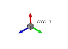
The basic information required to define a local system is its coordinate location and its orientation. Some construction methods reduce the amount of information required by the user to define a system, since the X,Y, Z coordinate location can be computed from an associative relationship like an offset (e.g. 45 degree offset on a circle), intersection, projection, or other associative relationship. Defining an associative relationship always requires a graphic mouse selection to determine the base object(s). Figure 2 illustrates a simple local Cartesian coordinate system definition and its visual representation. Note that there is a graphic embellishment of each principal axis of the local system. Each axis is displayed in a different color (X=blue, Y=green, Z=red).
Local cylindrical (R, θ, Z) and spherical (R, θ, φ) coordinate systems are visually represented like Cartesian systems and are indicated by a C or S, respectively. The coordinate system conventions used in StressCheck are illustrated in Figure 3.
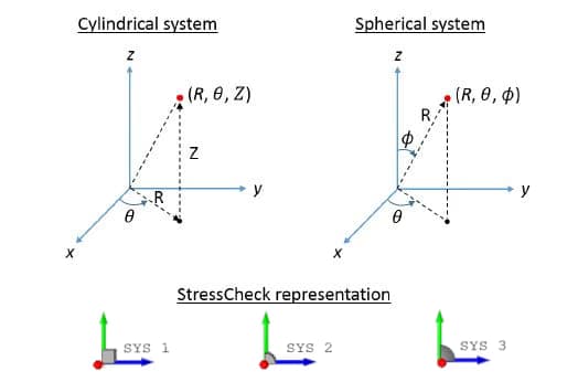
For cylindrical systems, the radius (R) is the distance from the z-axis to the point, the azimuth angle (θ) is measured counter-clockwise from the x-axis in the x-y plane, and the height (Z) is identical to its Cartesian counterpart. For spherical systems, the radial distance (R) is the distance from the origin to the point, the azimuth angle (θ) is measured counter-clockwise from the x-axis in the x-y plane, and the polar angle (φ) is measured from the z-axis to a line segment drawn between the origin and point.
Supported Methods
The following methods are supported for the creation of local system objects:
- 3-Pt Plane
- Delta
- Intersect-Multi
- Intersection
- Local
- Locate
- Mid-Offset
- Midpoint
- Offset
- Point
- Projection
- Sample
Consult the Primitive Geometry Creation Methods section for detailed descriptions.
Example: 3-Pt Plane Method
To create a Cartesian system passing through three points select Action: Create > Object: System > Method: 3-Pt. Plane, Data Type: Cartesian. The system is located at the position of the first pick point, the x-axis is in the direction of the line from point 1 to point 2, and the y-axis is in the direction of the line from point 1 to point 3. The z-axis will therefore be oriented normal to the plane defined by the 3 points, consistent with the right-hand rule.
Point Object
To create a Point object, set the C/A/O/M to Create > Point, and choose the desired method (see below for the supported methods).
Overview
The basic definition of a point is a geometric coordinate location X,Y, Z (R, Z in Axisymmetric analysis). Points will appear as a brown “+” symbol. Points may be created by several methods, and may be used as the basis for other associative objects such as lines, splines, circles, etc. Points are to be distinguished from nodes, which are element topological objects. Points cannot be used in the definition of an element, only nodes may be used in this way.
Supported Methods
The following methods are supported for the creation of point objects:
- Delta
- Intersect-Multi
- Intersection
- Local
- Locate
- Mid-Offset
- Midpoint
- Offset
- Projection
- Sample
Consult the Primitive Geometry Creation Methods section for detailed descriptions.
Line Object
To create a Line object, set the C/A/O/M to Create > Line, and choose the desired method (see below for the supported methods).
Overview
A line may be created in several ways. In parametric form, the X, Y, Z location of its starting point, its length, and orientation angle measured in degrees from the positive global X axis in the XY plane of the global or a local system are required. Figure 4 illustrates the visual appearance of a line object. Note: the local system does not need to be contained in the global XY plane, allowing line objects to exist in 3D space at arbitrary orientations.
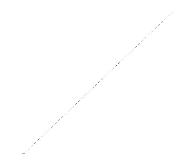
Note that a Point appears at the starting point so that it is possible to determine at a glance the direction of the line. Note also that curves and surfaces will appear dashed by default when element objects are enabled for display. This is so that if an element edge overlaps a curve, it will be possible to see the element edge showing between the dashes of the curve. If you wish to visualize curves as solid lines, you must disable elements from the Model View using the View > Display Objects Toolbar > Display elements. Lines are parameterized with a single parameter in the range 0.0 ≤P1 ≤ 1.0. This makes it easy to associate other objects with a line.
For example, if you wish to attach a point, system, or node to a line at a position 75% of the length from the starting point, simply specify an offset value of 0.75. This associative relationship will be maintained automatically. If the length or orientation of the line changes, the associated object will always stay at a position corresponding to 75% of the current length of the line. This associative relationship can be parametric.
Supported Methods
The following methods are supported for the creation of line objects:
- 2-Point: Select Create > Line > 2-Point. Pick two points, the first point picked will define the origin (P1=0.0) of the line.
- Locate: Select Create > Line > Locate. Enter X, Y, Z coordinates which locate the origin of the line. Enter the Length of the line. Enter the Orientation of the line relative to the selected coordinate system (default is Global) rotating CCW about the z-axis. The orientation angle is measured in degrees. Click on Accept.
- Normal: Creates a line normal to a selected line at a specified offset location on the line. A reference point is required to create a construction plane and establish the positive direction of the line. Select Create > Line > Normal. Enter a value for the Offset (origin location on the selected line) between 0 and 1. Enter the Length of the new line. Pick a line to which the created line will be normal. Pick a point (not on the selected line) that establishes the positive direction of the line.
- Off. Parallel: Creates a line parallel to a selected line at a given offset distance from the line. The length of the new line is measured from the origin (P1=0 position) of the line selected. Select Create > Line > Off. Parallel. Enter the Distance of the parallel offset. Enter the Length of the new line. Pick the reference line to which the new line will be created parallel. Pick a point (not on the reference line) that establishes direction of offset.
- Offset: Creates a line whose origin lies on a selected boundary object and is oriented relative to a specified coordinate system. Select Create > Line > Offset. Enter Offset value. Enter the Length of the line. Enter the Angle (measured in degrees). Pick a boundary object (line, surface curve, circle, spline, etc.) that is defined by a single parameter range (P1).
- Point: Creates a line with its origin at a specified point. This method is identical to the Locate method except the X, Y, Z coordinates are obtained by selecting a point. Select Create > Line > Point. Enter the Length of the line. Enter the Orientation of the line relative to the selected coordinate system (default is Global) rotating about the z-axis. The orientation angle is measured in degrees. Pick a point (origin of the line).
- Sample: Creates a line whose end points are at the P1min and P1max locations on a selected spline object. Select Create > Line > Sample. Pick a spline. Note: This method will not work with a closed boundary object (e.g. circle, fillet, ellipse, etc.) because P1min and P1max are the same point. You can use the X, Y, Z inputs to force the end points to be at a specified coordinate location. Values in any of these input boxes override the coordinates of the spline end points.
- Tan to 1 Pt.: Creates a line tangent to a circle passing thorough a point. Select Create > Line > Tan to 1 Pt. Pick the point. Pick the circle in the area to which the line is tangent.
- Tan to 2 Cir.: Creates a line tangent to two circles. Select Create > Line > Tan to 2 Cir. Pick the first circle. Pick the second circle.
- Work Plane: Creates a line which lies in a selected plane and its origin is located relative to the plane reference (local) system. Select Create > Line > Work Plane. Enter X. Enter Y. Enter the Length of the line. Enter Angle (measure in degrees). Pick the plane.
Circle Object
To create a wireframe Circle object, set the C/A/O/M to Create > Circle, and choose the desired method (see below for the supported methods).
Overview
The basic definition of a circle is a coordinate location of its center and a radius. By default, a circle is automatically created with a local system at its center so that it is easy to move the circle and to introduce an orientation in 2D or 3D space. Figure 5 illustrates the visual appearance of a circle object.
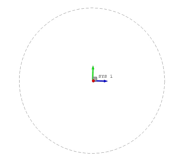
The circle object is parameterized as follows: 0.0 ≤ P1 ≤ 360.0 degrees. It is possible to create a circular arc by specifying a subset of the parameter range (e.g. 45 ≤ P1 ≤ 115). The location, radius, and parameter range of the circle may be parametric.
Supported Methods
The following methods are supported for the creation of circle objects:
- 3-Pt. Arc: A circular arc can be defined using the 3-Pt. Arc method. The three points together determine the orientation and radius of the circle. The first and last points selected define the range of the arc. The second point determines which side of the circle to represent with the arc.
- 3-Pt Circle: A circle may be defined by the 3-Pt Circle method in which the circle will pass through all three selected points.
- 3-Pt Circle(CRP): A circle may also be defined by the 3-Pt CRP (center, radius, point) method. In this case, the first point represents the center of the circle, the second point established the radius of the circle and the direction of the local x axis, and the third point establishes the plane in which the circle lies. The circle is a complete 360 degree circle.
- Delta
- Local
- Locate
- Offset
- Point
- Sample
Consult the Primitive Geometry Creation Methods section for detailed descriptions for Delta, Local, Locate, Offset, Point and Sample.
Ellipse Object
To create a wireframe Ellipse object, set the C/A/O/M to Create > Ellipse, and choose the desired method (see below for the supported methods).
Overview
The basic definition of an ellipse is a coordinate location of its center, a major axis radius and a minor axis radius. By default, an ellipse is automatically created with a local system at its center so that it is easy to move the ellipse and to introduce an orientation in 2D or 3D space. Figure 6 illustrates the visual appearance of an ellipse object.
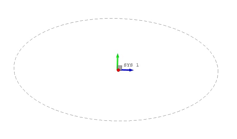
The ellipse object is parameterized as follows: 0.0 ≤ P1 ≤ 360.0 degrees. It is possible to create an elliptical arc by specifying a subset of the parameter range (e.g. 45 ≤ P1 ≤ 115).
Supported Methods
The following methods are supported for the creation of ellipse objects:
- Delta
- Local
- Locate
- Offset
- Point
- Work Plane
Consult the Primitive Geometry Creation Methods section for detailed descriptions.
Fillet Object
To create a wireframe Fillet object, set the C/A/O/M to Create > Fillet > Selection.
Overview
Like a circle object, the underlying definition of a fillet is a coordinate location of its center and a radius. However, the fillet is an associative object which is tied to two boundary curves. You need only to select the two curves and supply a fillet radius. The program will automatically compute the location of the center and the arc range of the fillet, and will also locate two points at the tangency locations. Figure 7 illustrates the visual appearance of a fillet object.
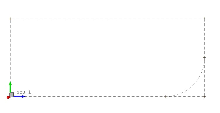
At present, fillets can be constructed between line objects and circle objects (i.e. two lines or one line and one circle), only.
Polyline Object
To create a Polyline object, set the C/A/O/M to Create > Polyline, and choose the desired method (see below for the supported methods).
Overview
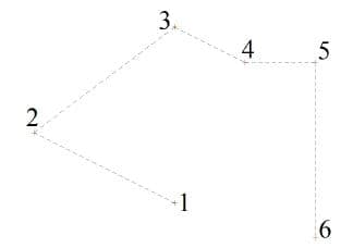
The polyline object is not a true independent object. It is actually composed of line objects which are associated with point objects. The polyline object is provided as a convenient tool for constructing a series of straight lines connecting points. Figure 8 illustrates the visual appearance of a polyline object.
Supported Methods
The following methods are supported for the creation of polyline objects:
- Locate
- Point
- Work Plane
Consult the Primitive Geometry Creation Methods section for detailed descriptions.
Example: Point Method
Try to construct a polyline as the one shown in Figure 7. First, create 6 arbitrary points, then select Geometry tab > Action: Create > Object: Polyline > Method: Point. Now, click once on each of the points, in the desired order, but double-click on the last point to indicate the end of your selection.
Spline Object
To create a wireframe Spline object, set the C/A/O/M to Create > Spline, and choose the desired method (see below for the supported methods).
Overview
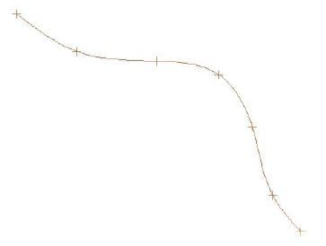
The spline object is a rational spline curve which may be constructed by five different methods: Fit-Auto, Locate, Point, Offset, and Mid-Offset. Figure 9 illustrates the visual appearance of a spline object.
Supported Methods
- Fit-Auto: Use the Fit-Auto method to construct a spline curve passing through existing points. Holding the left mouse button down “draw” a rectangle around the area of interest in order to select the points, then click on the Accept button.
- Locate/Point: Use the Locate method to construct the spline curve by locating a series of points at new locations in model space. Use the Point method to construct the spline curve by selecting a series of existing points. For the Locate or Point methods, click twice on the last location or point to complete the construction. The polynomial order of the spline is assigned automatically. The spline will pass through all points. The spline object is parameterized as follows: 0 ≤ P1 ≤ 1.0.
- Offset: Use the Offset method to construct a spline curve which is at a fixed distance from a reference curve. A series of sample points, the number of which is specified as an input value (Res:), is computed on the reference curve. The normal to the curve at each point is computed and a construction point is located on the normal vector at a fixed distance from the reference curve as specified by the input “offset” value as follows:
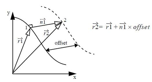
The computed construction points are then used to construct the new spline curve. The resulting spline curve maintains an associative relationship with the reference curve. The offset value may be parametric. Note: the Repeat feature may be used to construct several spline curves with one construction operation. The Offset method may be used to construct a spline associated with all selected curves by entering the appropriate input and clicking on the Accept button.
- Mid-Offset: Use the Mid-Offset method to construct a spline curve which is positioned relative to two reference curves. A series of sample points, the number of which is specified as an input value (Res:), is computed based on sample points taken from the reference curves. Moving along each curve from the initial offset to the final offset, a sample point is taken and a new construction point is computed as follows:
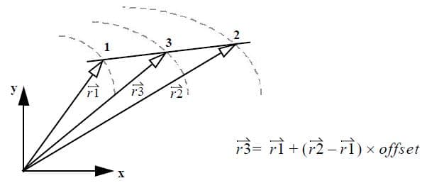
If the offset value provided is 0.5, each point on the resulting spline curve will be equidistant from the reference curves. The resulting spline curve maintains an associative relationship with the reference curves. The offset value may be parametric. To construct the mid-offset curve, click once on each of two curves. If the resulting curve is twisted, it may be necessary to use the Select/Boundary/Reverse technique to reverse one of the curves.
Formula Object
To create a wireframe Formula object, set the C/A/O/M to Create > Formula, and choose the desired method (see below for the supported methods).
Overview
The formula object is a curve defined by formulas which determine the value of the X, Y, and (optionally) Z coordinates of the curve with respect to a single independent variable. The independent variable is controlled by the parameter P1, in which the range of inputs into the formulae are controlled by P1-Min and P1-Max. The formula object will be associated automatically with a local system in which the dependent variables (X,Y,Z) will be evaluated. This also makes it possible to easily orient the curve after it is created.
Figure 12a represents the formula expressions (xfmla, yfmla) used to generate the formula object, and Figure 12b represents the formula input fields for C/A/O/M Create > Formula > Locate. Figure 12c illustrates the visual appearance of the resulting formula object.
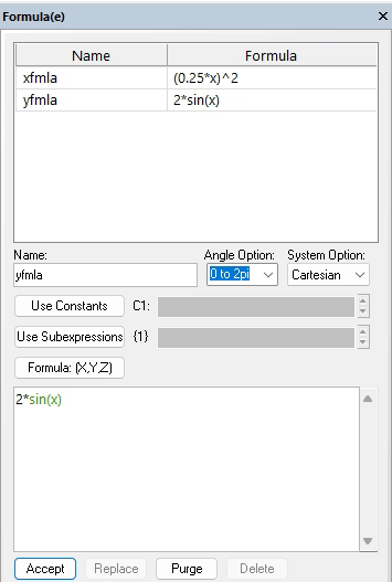
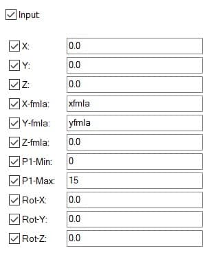
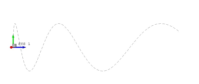
The formula object is parameterized as follows: P1-Min ≤ P ≤ P1-Max.
Supported Methods
- Local
- Locate
- Offset
- Point
Consult the Primitive Geometry Creation Methods section for detailed descriptions.
Rectangle Object
To create a wireframe Rectangle object, set the C/A/O/M to Create > Rectangle, and choose the desired method (see below for the supported methods).
Overview
The rectangle object is not a true independent object. It is actually composed of four line objects which are associated with four point objects, which are attached to a local system object. The rectangle object is provided as a convenient tool for constructing a rectangular shape. It may be defined as constant or parametric, and once created, may be rotated by rotating the underlying local coordinate system. See Figure 13 for an illustration of a rectangle object definition.
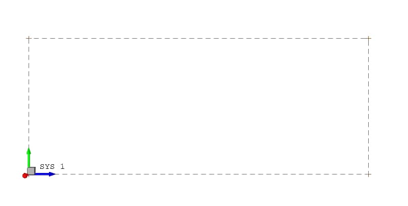
Supported Methods
- 2-Point
- Locate
- Offset
- Point
Consult the Primitive Geometry Creation Methods section for detailed descriptions.
Label Object
To create a Label object, set the C/A/O/M to Create > Label, and choose the desired method (see below for the supported methods).
Overview
The Label object is used to display a text label on the screen at a location identified by the mouse cursor. Enter the desired text in the Label: field in the input area, then trace a line on the screen to indicate the location of the label. You may also adjust the font style and font size for the label by clicking the Font… button. See Figure 14 for an illustration of a Label definition.
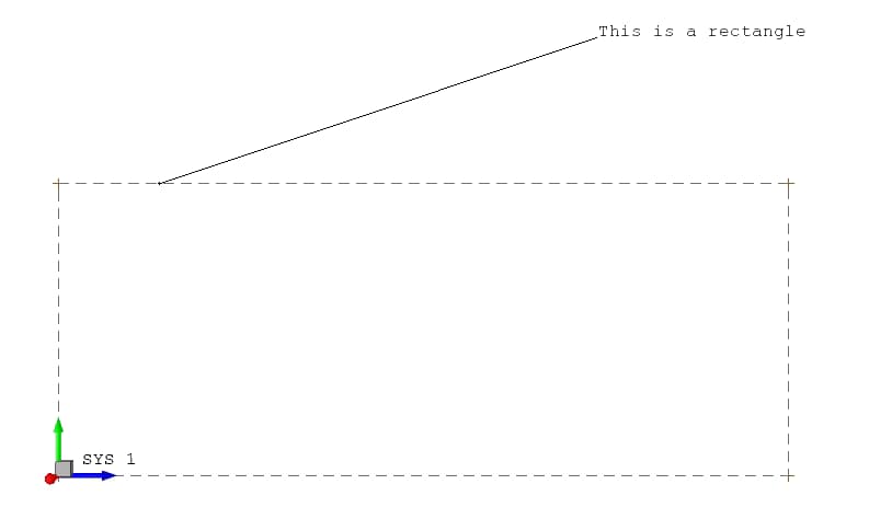
Supported Methods
- Delta
- Intersection
- Local
- Locate
- Mid-Offset
- Midpoint
- Offset
- Point
- Work Plane
Consult the Primitive Geometry Creation Methods section for detailed descriptions.
Composite Curve
To create a Composite Curve object, set the C/A/O/M to Create > Comp. Curve > Selection.
Overview
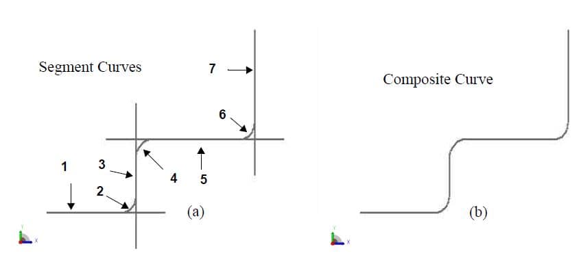
A composite curve is defined by connecting some number of 2D curves into a single composite curve. The resulting curve may subsequently be used to construct a tabulated cylinder, surface of revolution, ruled surface, or spline surface. The curve coordinates are defined in the range 0 ≤ P1 ≤ 1. The curve coordinates may be understood to be a fraction of the defined curve length.
Example: Composite Curve from Seven (7) Segments
To construct a composite curve in StressCheck requires that you first construct the 2D curve segments as illustrated in Figure 14, then trim the curves by choosing Select > Any Curve > Trim to Curve, clicking on each curve to be trimmed, and clicking on the point where that curve intersects the fillet. Finally, choose Create > Comp. Curve > Selection, and select the curves with the mouse cursor in the desired order. Double-click on the final curve to complete the definition. Be sure to select the segment of the curve you wish to include in the definition. The composite curve will be constructed by identifying the intersection points between each curve segment and attaching the segments end to end at the intersection points. The points of selection (see pick points labeled 1-7 in Figure 15) on each curve segment should be in the range of the curve which is intended to become part of the composite curve.
Surface Curve
To create a Surface Curve object, set the C/A/O/M to Create > Surf. Curve, and choose the desired method (see below for the supported methods).
Overview
A surface curve is a curve attached to one or two surfaces which has an associative relationship with those surfaces. The surface curve may be created by one of three methods. It may be created as an intersection of two surfaces, as a projection of a secondary curve to a surface, or as a trace along the surface between two points which have been projected to the surface. The surface curve retains its associativity with the parent points, curves and surfaces, so that if the dimensions or locations of the objects are changed, the surface curve will be recomputed automatically.
If a node is attached to the surface curve, the underlying associativity with the objects is inherited by the node so that when an element is attached to the node, element edges and/or faces will be properly associated with the objects for the purposes of geometry and boundary conditions.
Supported Methods
- 2-Point: A surface curve representing the trace between two points which have been projected to a surface may be constructed by selecting Create > Surf. Curve > 2-Point. Use the mouse to select first the surface, then the two points to be projected.
- Intersection: A surface curve representing the intersection between two arbitrary surfaces may be constructed by selecting Create > Surface Curve > Intersection. Use the mouse to select the two surfaces to be intersected. The location of the mouse pick should be in close proximity of the desired intersection curve so that if there is more than one intersection between the surfaces, the program will construct the desired curve.
- Projection: A surface curve representing the projection of a secondary curve to a surface may be constructed by selecting Create > Surf. Curve > Projection. Use the mouse to select first the surface, then the curve to be projected.
 Serving the Numerical Simulation community since 1989
