Tip: Start typing in the input box for immediate search results.Can't find what you're looking for? Submit a support request here.
3D Load Methods
3D Load Methods in StressCheck
In 3D elasticity, the following methods are available for assignment of loads to nodes, points, geometric surfaces, element faces, solid bodies, mesh regions (i.e. enclosed surfaces) and/or tetrahedral/pentahedral/hexahedral elements. The supported object types for each method will be listed below each method description.
For example, the following animation demonstrates the assignment of a 3D Bearing load to a cylindrical surface and appropriate local system, and the resulting normal sinusoidal traction distribution:
For more details on load inputs, load assignments and checking static equilibrium of assigned loads, refer to Loads Overview.
Traction
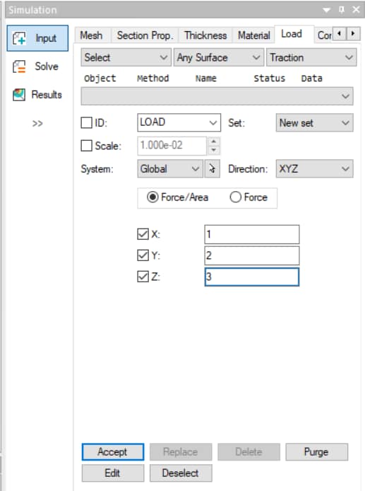
A distributed load (in force per unit area) is imposed on a geometric surface or element face. If the traction is attached to a surface, all the element faces associated with that surface will be loaded.
Traction is a vector quantity, and therefore three components must be given. These may be in the normal-tangent reference frame, in the global system, or an arbitrary local system. If the reference frame is the normal-tangent then only a normal traction can be applied as the tangent directions are not defined in 3D.
Two input options are provided, the “Force/Area” (default) for traction components or “Force”. The “Force” input is internally converted to traction loads by dividing the input load by the area of the element faces resulting from the selected objects (Face, Face Surface and Any Surface).
Object Types:
- Any Surface
- Face
- Face Surface
For a tutorial on traction loads, refer to StressCheck Tutorial: Traction Load.
Note: traction loads can also be applied to thin solid (shell) and beam elements if the object Any Curve, Edge or Edge Curve is selected in the user interface (Shell Traction and Beam Traction, respectively). In the case of thin solids and beams, tractions are in force per unit length.
Bearing
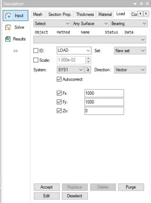
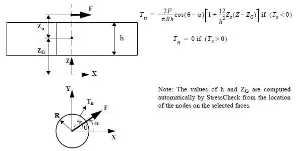
Bearing loading means that a normal sinusoidal traction (representing the interaction of a neat fit pin or fastener with a plate) is applied to a cylindrical hole by specifying the force vector components (Fx, Fy) or force magnitude/ angular direction. 3D bearing loads can be applied to a single cylindrical surface or to a group of surfaces in a cylindrical pattern.
- A coordinate system must be selected with the z-axis directed along the center of the cylinder.
- The angle under the Mag/Dir option is measured from the positive x-axis of the system (positive counter clockwise).
- Finally, the position of the bearing resultant along the z-axis must be provided under the Zo-input. Zo=0 means that the resultant is applied at the mid-height of the hole. If Zo is different from zero, then the applied traction will include the effect of bending.
- The traction applied to the element faces around the hole is determined from the following equation:
- The Autocorrect option (enabled by default) is used to account for variations on the selection with respect to a perfect cylinder (e.g., non-cylindrical holes or suboptimal meshes). When the resultants loads of the bearing traction distribution (that assumes a perfect cylinder) computed over the elements associated with the selection is different than the input loads, corrective tractions are added to the Bearing load distribution in order to compensate for the differences.
- When the Auto-correct option is checked the circularity and taper tolerances are still checked, but in the case of circularity relaxed to a looser value (0.5 instead of 0.01).
Object Types:
- Any Surface
- Face
- Face Surface
For a tutorial on bearing loads, refer to StressCheck Tutorial: Bearing Load.
For details on 3D bearing load equations, requirements and automatic corrections for non-cylindrical holes, refer to What are the 3D Bearing Load Requirements? and StressCheck Tutorial: Autocorrect for Bearing and TLAP-Bearing Loads.
Force/Moment
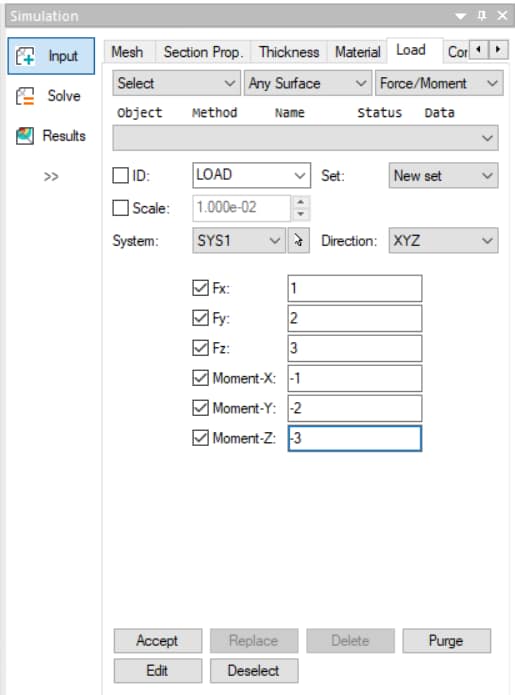
Force/Moment loading means that the directional components of force and moment vectors defined on a local system are applied to a flat co-planar surface as a statically equivalent linear traction distribution.
Object Types:
- Any Surface
- Face
- Face Surface
For a tutorial on Force/Moment loads for arbitrary flat cross sections, refer to StressCheck Tutorial: Usage of the Force/Moment Method for Arbitrary Cross Sections.
For more details on the Force/Moment load implementation, refer to StressCheck Tutorial: Force/Moment Load.
Spring Displacement (Spring Disp.)
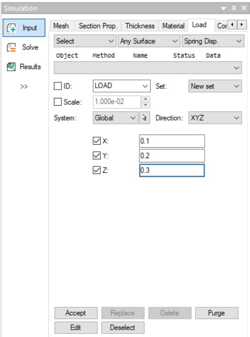
Spring displacement means that a traction load is applied through a displacement imposed on a distributed spring which has been specified on a surface or element face. The only restriction is that the spring coefficients and the imposed spring displacements must be in the same reference frame (i.e. Norm./Tan. → Norm./Tan.). Spring displacements are in units of length.
Spring displacements may be applied in directional (XYZ) or normal-tangent (Norm./Tan.) reference frames, in the Global or a local system. If Norm./Tan. reference, only a Normal spring displacement may be applied (the tangent directions are not defined in 3D). Normal spring displacements may be useful in representing interference fits in holes for 3D cold-working analyses.
Object Types:
- Any Surface
- Face
- Face Surface
For a tutorial on spring displacement loads, refer to StressCheck Tutorial: Spring Displacement Load.
Body Force
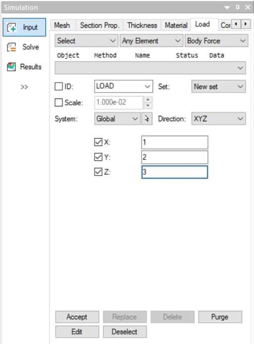
Body force loading means that the body is loaded by some volumetric load (in force per unit volume), such as by gravity or inertia due to acceleration. If the acceleration vector a={ax, ay, az} and the mass density (ρ) are known then enter the products: X = axρ, Y = ayρ and Z = azρ.
Body forces can be applied to solid bodies, or tetrahedral, pentahedral or hexahedral elements in the global or any local Cartesian coordinate system. 3D body force loads may be useful when loading cylindrical pins in holes.
Object Types:
- Any Body
- Any Element
- All Elements
- Mesh Region
For a tutorial on body force loads, refer to StressCheck Tutorial: Body Force Load.
Thermal
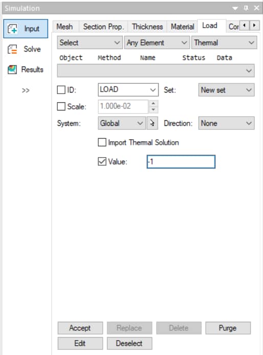
Thermal loading means that a temperature distribution (in degrees) will be specified on elements. Temperature distributions obtained from a heat transfer analysis are also available in 3D.
Object Types:
- Any Body
- Any Element
- All Elements
- Mesh Region
For an example of using thermal loads for bolt-preload modeling, refer to Helpful Hints and Tips: Application of Bolt-Preload via Multi-Body Contact.
Point Force
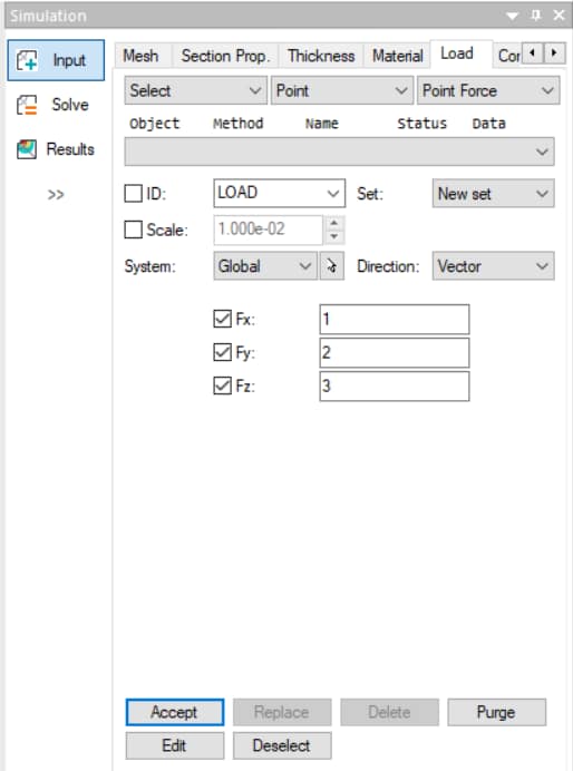
Point force means that a location on the elastic body is loaded by a concentrated force. Point forces may be applied in the global or any local Cartesian coordinate system.
Object Types:
- Point
- Node
For tips on using point forces/loads in 3D elasticity, refer to Helpful Hints and Tips: Using Point Loads in StressCheck.
Note: the use of point forces in 3D elasticity will result in stress singularities at/around the point location. Refer to StressCheck Tutorial: Detecting Stress Singularities for details.
TLAP Traction
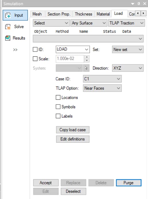
Total point loads (TLAPs) obtained from the solution of a global model can be associated to faces or to surfaces of a solid model which are not part of a hole. The total point force/moment (in force/force-length units) is converted into tractions distributed over each face such that they are statically equivalent to the corresponding point load/moment.
Object Types:
- Any Surface
- Face
- Face Surface
For a tutorial on TLAP Traction loads vs uniform Traction loads, refer to StressCheck Tutorial: TLAP-Traction vs Uniform Traction Case Study.
For more details on the TLAP-Traction implementation, options and applicability, refer to Total Load at a Point (TLAP) Implementation, What Is The Applicability Of TLAP-Traction?, What’s the Difference Between TLAP-Traction Options Near Faces and All Faces?, and Why Are There Stress “Spikes” in My TLAP-Traction Application Surface?.
TLAP Bearing
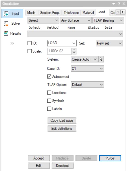
This functionality allows for the importation of total load at points (TLAPs) representing fastener loads obtained from the solution of a global model, and their assignment to a set of selected faces or the surface of a solid model associated with a hole or bore. The fastener load force/moment (in force/force-length units) is converted into bearing tractions distributed over the surface of the hole.
- Specification of a local system with Z-axis parallel to the hole is required (similar to the Bearing method); if a local system with those requirements does not exist, setting System: Create Auto will generate a system with the required orientation.
- Two options are provided: “Default” which generates a statically equivalent bearing load and “IMO” (Ignore Moments and Offsets) which generates a bearing load that ignores the contribution of the original point load moment components and the moments caused from the offset distance between the location of the selected TLAP(s) and the center of the hole.
- The Autocorrect option (enabled by default) is used to account for variations on the selection with respect to a perfect cylinder (e.g., non-cylindrical holes or suboptimal meshes). When the resultants loads of the bearing traction distribution (that assumes a perfect cylinder) computed over the elements associated with the selection is different than the input loads, corrective tractions are added to the Bearing load distribution in order to compensate for the differences.
- When the Auto-correct option is checked the circularity and taper tolerances are still checked, but in the case of circularity relaxed to a looser value (0.5 instead of 0.01).
Object Types:
- Any Surface
- Face
- Face Surface
For a tutorial on TLAP-Bearing loads, refer to StressCheck Tutorial: Converting TLAP-Tractions in a Hole to a Single TLAP-Bearing.
For more details on the TLAP-Bearing implementation, options and autocorrection feature for non-cylindrical holes, refer to Total Load at a Point (TLAP) Implementation, StressCheck Tutorial: TLAP-Bearing Default vs Ignore Moments & Offsets (IMO) Case Study, What is the Difference Between TLAP-Bearing Options IMO and Default? and StressCheck Tutorial: Autocorrect for Bearing and TLAP-Bearing Loads.
SRS System
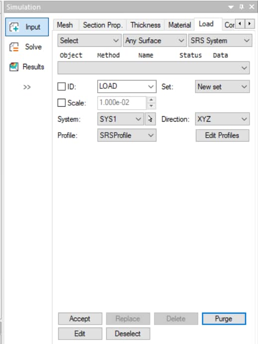
A subsurface residual stress/strain load (SRS) refers to a thin layer of residual or initial stress/strain just below the outer surfaces of a part, for example, due to high speed machining or shot peening. The stress distribution must be self-equilibrated in order to be a called residual stress distribution. SRS System refers to the usage of a Cartesian coordinate system (System: combo-box) for defining the local orientation of the distribution.
Object Types:
- Any Surface
- Any Element
- All Elements
SRS Curve
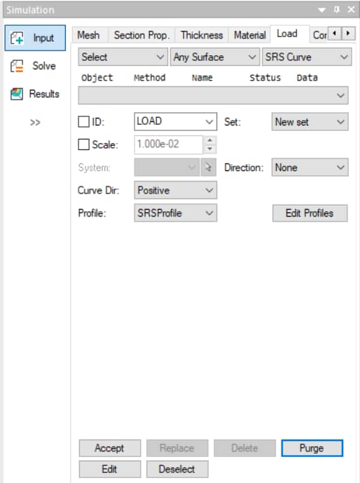
A subsurface residual stress/strain (SRS) load refers to a thin layer of residual or initial stress/strain just below the outer surfaces of a part. SRS Curve refers to the usage of a geometry curve for defining the changing local orientation of the SRS distribution.
Object Types:
- Any Surface
For a tutorial on SRS loads, refer to StressCheck Demo: 3D Subsurface Residual Stress (SRS) Distortion Analysis.
For more details on SRS, refer to Subsurface Residual Stress (SRS) Overview.
BRS
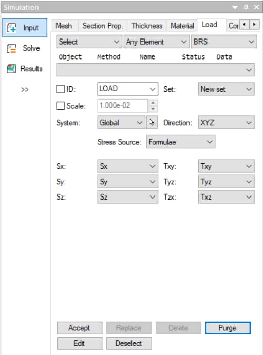
A bulk residual stress (BRS) load refers to residual stresses defined throughout the volume of material. The residual stress data may be imported into StressCheck or computed with the StressCheck incremental plasticity solver.
Object Types:
- Any Body
- Any Element
- All Elements
- Mesh Region
For a tutorial on BRS loads, refer to StressCheck Tutorial: Mapping Cold Working Residual Stresses to a Reamed Part via BRS Method.
For more details on BRS, refer to Bulk Residual Stress (BRS) Overview.
 Serving the Numerical Simulation community since 1989

