Tip: Start typing in the input box for immediate search results.Can't find what you're looking for? Submit a support request here.
Automatic Laminate Builder
Introduction
Automatic lamination refers to a discretization algorithm that constructs a laminated ply-by-ply mesh (child mesh) based on a manually constructed mesh of the full laminate thickness (parent mesh) and on material stack information. The process automatically creates ply-by-ply elements when a laminate stack of an arbitrary number of plies is assigned to group of parent elements. The parent mesh can be straight sided or curved hexahedral or pentahedral elements in 3D or quadrilateral or triangular elements in 2D.
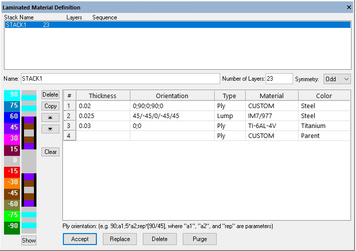
The layout of the Laminate Material Definition interface is designed to facilitate the description of a parametric laminate stack, to display visual feedback of the material attributes for each ply, and to automatically assign material properties to the child mesh based on attributes described in the stack description. Before defining a stack record, at least one material record must be defined. An example of a stack within the Laminated Material Definition interface is shown in Figure 1:
Note: to modify the font properties of the Laminated Material Definition table columns, right-click on any column label and then click “Select Font…”.
Automatic Lamination Procedures
The automatic discretization algorithm is based on identifying the parent element edge (Planar) or face (3D/Extrude) and specifying in which direction the stack is to be constructed, using the selected edge/face as the base of the stack or as the top. The parent element is subdivided in standard coordinate space, in proportion to the thickness of each ply as defined in the associated stack definition.
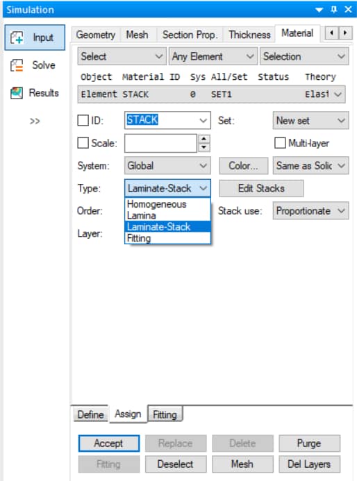
To access this feature, a particular interface must be used for laminated material definitions. The Laminated Material Definitions interface can be accessed by using Edit > Laminate Info in the Main Menu, or by selecting Type: Laminate-Stack in the Material Assignment interface and then clicking the Edit Stacks button as shown in Figure 2.
Once a stack is defined using the Laminated Material Definition interface it can then be assigned to the model via the automatic discretization process discussed under Stack Assignment Procedure.
Laminated Material Definition Interface Overview
The layout of the Laminated Material Definition interface (Edit > Laminate Info) is designed to facilitate the description of a parametric laminate stack, to display visual feedback of the material attributes for each ply, and to automatically assign material properties to the child mesh based on attributes described in the stack description. Before defining a stack record, at least one laminated material record must be defined.
Defining a Laminate Stack Record
To define a stack record, the following information is needed from the user:
- Stack Name: An alphanumeric entry to define the name of the stack (example: Stack1, or STK01).
- Number of Layers: A constant or parameter representing the total number of plies in the stack (example: NLayers, where NLayers is a parameter). If the number of layers is less than the number of plies defined in the ply records, then the first NLayers entries will be used by the program to construct the stack. The only exception to this rule is in the case of symmetric stacks.
- Symmetry: Controls whether ply symmetry in the stack assignment is utilized. The options are:
- None: No symmetry will be utilized (default), and the plies will be assigned exactly as shown by the specified ply records.
- Even: Even symmetry means that the first NLayers/2 plies of the ply records will be used to construct the laminate stack. When even symmetry is selected, then the input given in Number of Layers must be also even.
- Odd: Odd symmetry means then the first (NLayers-1)/2 plies of the ply records will be repeated around the (NLayers-1)/2+1 ply to construct the laminate stack. When odd symmetry is selected, then the input given in Number of Layers must be also odd.
- Ply Record: Each ply record describes the location, orientation(s), discretization instructions, and properties within the stack:
- Rec #: Indicates the ply record number.
- Thickness: Ply thickness. This may be a constant or user-defined parameter. If multiple plies are represented in one record, the thickness parameter describes the thickness of each individual ply within the record.
- Orientation: Ply orientation, in degrees, with respect to a given coordinate system or reference edge. It may be a constant or a user-defined parameter. The ply orientation can also be a parametric expression describing one or more plies of the given thickness. Multiple ply orientations may be specified for a single ply record if they are separated by either “;” or “/” (e.g. 90;0;90;0 or 90/0/90/0).
- Type: The options are ply or lump. If the type is “ply”, then the corresponding plies are represented by individual child elements. If the type is “lump”, then the corresponding plies are not represented individually, but are lumped together and represented by homogenized material properties.
- Material: Specify the material properties definition for the ply record by selecting from the pull-down menu. Only materials defined as Laminated Isotropic and Laminated Orthotropic are available for selection. At least one material property record must be defined in order to specify a ply record material.
- Color: Determines the visual representation color of the ply record. The default is the color of the parent element.
Command Buttons and Visual Feedback
The command buttons directly to the left of the ply record interface are used for copying an existing ply in to the last row of the table, deleting an existing ply, moving a ply specification upward or downward in the table, or clearing all ply records from the current stack record.
To the left of the command buttons is the stack layup color representation with each color corresponding to the principal direction of the corresponding ply and with the height of the color bar proportional to the ply thickness. This is helpful in determining how the input ply records are interpreted by the program. The lay-up is defined from bottom to top, such that the first ply record is at the bottom of the stack. The left-most color bar is a key identifying the ply angle in each ply.
At the bottom of the Laminate Material Definition interface there are stack record command buttons. These buttons may be used to add, change, delete, or purge stack records. Once the aforementioned input parameters are specified the user may click “Accept” to generate the stack record. The stack is now ready to be assigned to a set of elements.
Stack Assignment Procedure
Once a laminate stack record has been defined, it can be assigned to an element or group of elements. The program can then automatically discretize the parent element(s) into the necessary child elements of the assigned stack.
Laminate-Stack Type Options
To assign a laminate stack select the Assign tab of the Material interface, select the object Any Surface, Face or Face Surface (3D) or Edge or Edge Curve (Planar) and then change the Type to Laminate-Stack and complete as follows:
- ID: Select the name of the laminate stack record from the pull-down menu.
- System: The coordinate system defining the laminate material directions (only needed if reference edges are not selected to determine the principal material direction via laminate mapping).
- Order: Determines the order of the plies when the stack is assigned. The options are “Normal”, which means that the plies will be assigned as defined, starting from the face opposite to the one selected, or “Invert”, meaning the ply order will be inverted when assigned. The default is “Normal.”
- Stack: Determines how the stack is assigned to an element or group of elements. There are two automatic lamination methods available, Proportionate and Distributed:
- Proportionate: Every ply in the stack will be assigned to each element identified for assignment. If the total thickness of the stack is greater or less than the thickness of a parent element, then the plies will be proportionately scaled such that the thickness of the stack equals the thickness of the parent element. This is the default method.
- Distributed: Allows for the distribution of a laminate stack through one or more parent elements through the thickness of the laminate; there is no scaling of ply thickness. What is necessary from the user are stack thickness references (Base values). These Base values describe locations in the stack where an element edge or face exists. Additionally, users must select an edge or face to identify the element for laminate stack assignment.
- Layer: Optional identifier to control the display of the resulting child mesh (blank by default).
Object Selection and Stack Processing
After all the necessary information has been entered, an assignment may be made by specifying an element edge or edges (Planar) or a geometric surface or surfaces, element face or faces, or element face surface (3D) and clicking on the Accept button. To process the stack assignment click on the Mesh button. The mesh will be updated to show the resulting stack assignment.
The following animation demonstrates the assignment of a 10-ply distributed laminated stack definition to two elements with combined thickness 1″, with the second element at Base=0.75″:
Note that wetted faces were disabled and shrink elements was enabled to facilitate the selection of internal element faces.
Principal Direction Specification
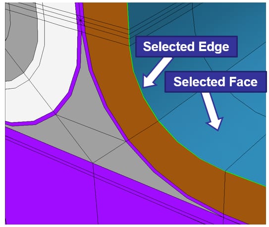
Alternatively, for extruded or 3D elements, once the assignment objects have been selected the user may hold the Ctrl + Shift keys and click to select a reference geometric curve or curves (if Any Surface is the object assignment type), one or more element edges (if Face is the object assignment type), or an edge curve (if Face Surface is the object assignment type) to map the laminate principle direction to the selected geometric curve(s)/edge(s)/edge curve. A mapped laminate stack assignment will follow the Lam-Map Edge mapping algorithm:
For an example of assignment of a laminate stack using Any Surface and a reference geometric curve, refer to StressCheck Tutorial: Laminated Shaft with Helical Fiber Orientation.
Mesh Layer Visualization
To toggle between the final (child) mesh and original (parent) mesh, use the Display Mesh Layers button on the Display Objects toolbar:

The pull-down menu will contain the list of the names that were input under “Layer” to display specific groups of child elements. If modifications are be made to an existing record, such as changes in the number of plies, ply thickness, etc., click on the Mesh button to update the model. If the child mesh corresponding to an assignment record must be deleted, but the record kept, click on the Del Layers button. In order to view the ply orientations by color coordination, or verify a stack assignment, select the Display Materials toggle in the Attributes toolbar, and activate Colors from the pull-down menu. A legend will be displayed to relate ply orientation with the colors.
Stack Use: Proportionate vs Distributed Automatic Lamination
To demonstrate the use of Proportionate and Distributed automatic lamination for problems in 3D Elasticity, two simple example problems will be discussed in the following.
Proportionate Automatic Lamination
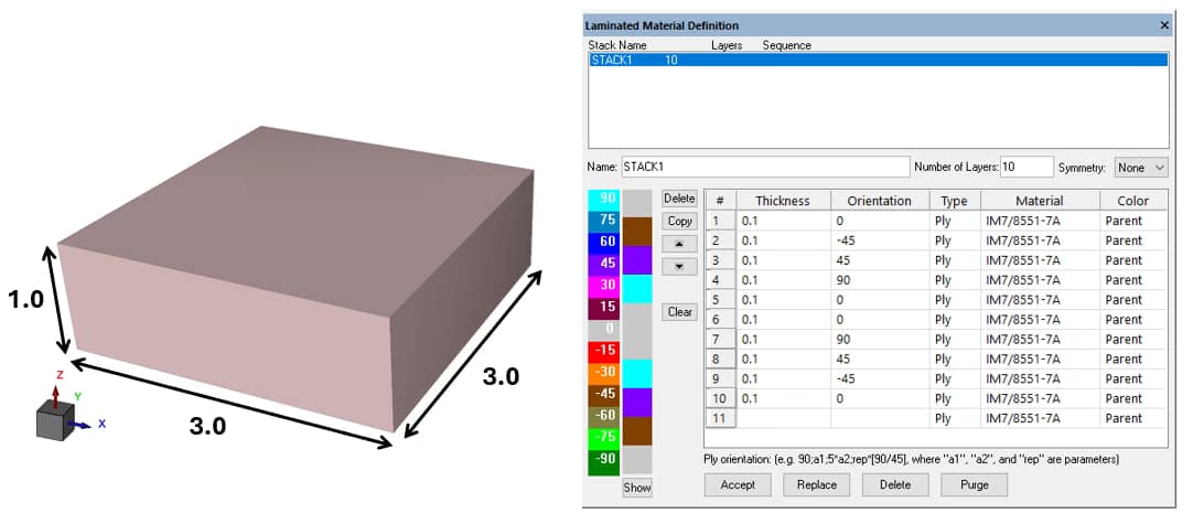
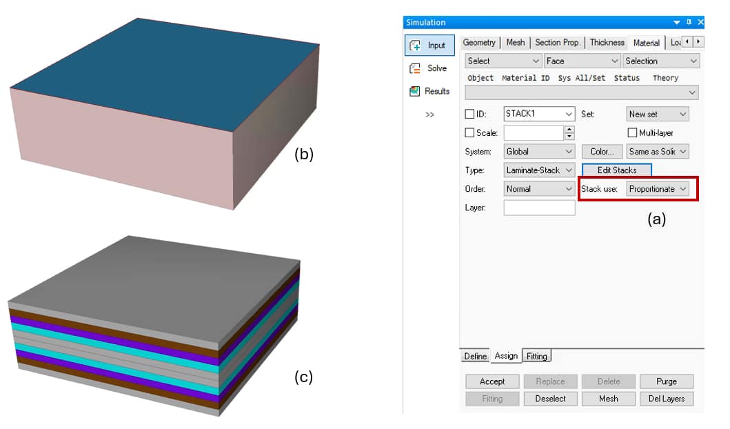
The thickness of the element is defined as 1.0 and the width and height as 3.0, shown below in Figure 3. A laminate stack (STACK1) of 10 plies has been defined such that all of the plies are of the same thickness (0.1). All the plies are of the same orthotropic material IM7/8551-7A Prepreg RT Dry:
To create the assignment records select the Assign tab in the Material input interface and complete as follows:
- Select > Face > Selection. Select the top face of the element as shown below in Figure 4b, set Order: Normal such that the stack will be assigned starting from the opposite face to the one selected, and set Stack use: Proportionate to ensure all plies are proportionately scaled to fit within the 1″ parent element (Figure 4a). Then click on Accept to add the automatic lamination assignment.
After clicking the Mesh button, the child mesh should be as shown below in Figure 4c. The original element was split into 10 layers (child mesh). For the Proportionate Automatic Lamination method to correctly assign the plies, the sum of the ply thicknesses in the stack must be equal to the thickness of the parent element to which the stack was assigned.
If these values are not equal, a warning will be issue by StressCheck informing the user that the plies have been proportionately scaled to fit the element thickness. Proportionate Automatic Lamination is best suited for domains which are only one element through the thickness of the laminate.
Distributed Automatic Lamination
In the case of multiple parent elements through the thickness, distributed automatic lamination must be used for assigning a laminate stack record. The input data include the stack thickness reference (Base) and the face(s) defining the element(s) to be assigned. This ensures that the stack plies are split properly when a stack assignment to a parent element is made.
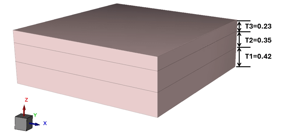
Consider three elements through the thickness of the laminate and the assignment of the stack record of the previous example, with 10 layers 0.1 thick over the total thickness of the laminate. The total thickness of the model is 1.0, and lower parent element is of parametrically defined thickness T1=0.42, the middle parent element is of thickness T2=0.35 and the upper parent element is of thickness T3=0.23, shown below in Figure 5. Each parent element will be assigned the appropriate portion of STACK1:
To create the assignment records select the Assign tab in the Material input interface. To facilitate the selection of the appropriate faces, turn off Wetted Surfaces from the Display Options tool bar, turn on Shrink Elements and then complete as follows:
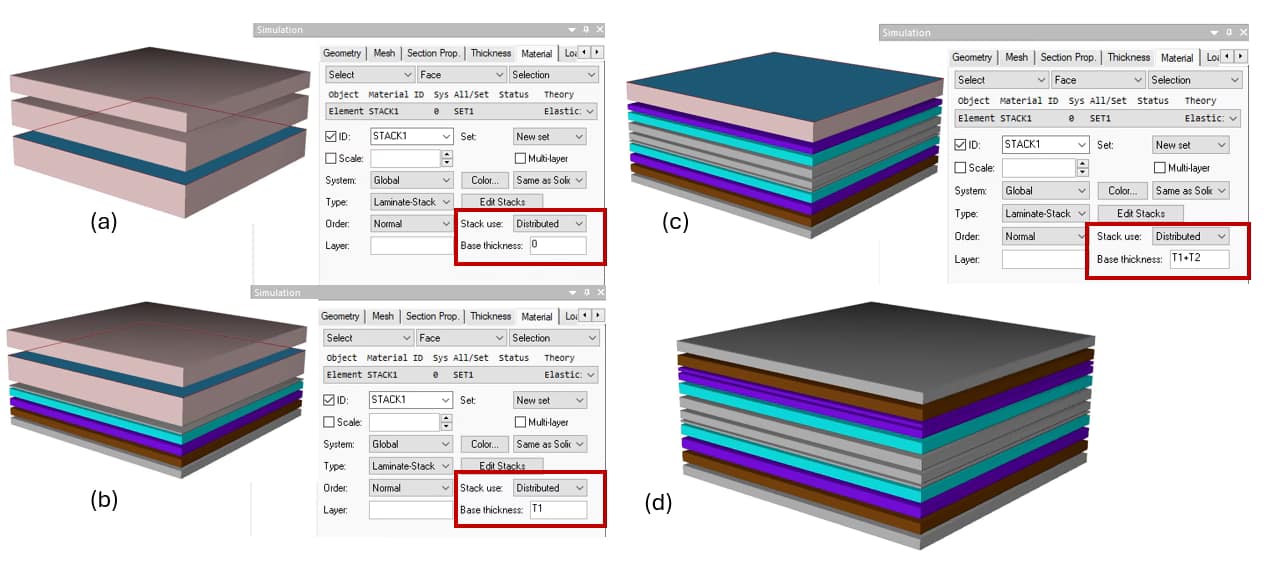
- Select > Face > Selection. Select the top element face of the bottom parent element as shown below in Figure 6a. Set Order: Normal such that the stack will be assigned starting from the opposite face to the one selected, set Stack use: Distributed to allow distribution of the stack definition through multiple parent elements, and set Base: 0 (origin of STACK1) is defined to be at the base of the lower element. Click on Accept to assign a 0.42 portion of STACK1 to the lower parent element.
Next, the middle parent element is selected for assignment:
- Select > Face > Selection. Select the top element face of the middle parent element as shown in Figure 6b. Set Order: Normal, Base: T1 and click on Accept to assign a 0.35 portion of STACK1 to the middle parent element.
The remainder of STACK1 is assigned to the upper parent element, in which case the Base value should be T1+T2 (0.77). Select the face of the upper parent element for assignment as shown in Figure 6c and enter a Base of T1+T2, then click on Accept. Finally, click the Mesh button to process the three automatic lamination assignments.
The final mesh corresponding to the complete assignment of STACK1 to all three layers of parent elements is shown in Figure 6d. Note that the fifth ply in the stack was split at the shared face between the first and second parent element such that two child-elements are needed for that ply. In the same way, ply #8 is split at the interface between the second and third parent elements:
For examples of automatic lamination for laminated composites analysis, refer to StressCheck Tutorial: Laminated Composite Repair Patch Part I: Geometry and Meshing and StressCheck Demo: 3D Laminated Composites Analysis.
 Serving the Numerical Simulation community since 1989

