Tip: Start typing in the input box for immediate search results.Can't find what you're looking for? Submit a support request here.
Crack Path Analysis Overview
2D Crack Path Analysis in StressCheck
Crack Path analysis is limited to use with 2D planar domains and requires that a set of model construction rules be carefully followed. In contrast to other analysis modules in StressCheck, Crack Path analysis does not require that the user construct a finite element mesh in advance. Rather, the analysis procedure will automatically mesh the domain during the solution process.

Note: to modify the font properties of the Crack Path table columns, right-click on any column label and then click “Select Font…”.
Implementation
The current implementation of Crack Path analysis computes through-crack stress intensity factors for mode I and mode II along a predicted crack propagation path. This functionality is applicable to planar analysis (2D plate with in-plane loading). The trajectory of the crack is determined by a relationship between mode I and mode II SIF’s (K1 and K2) and is shown to be very accurate.
The formulation of the trajectory equation is based on two commonly recognized hypotheses, proposed in “On the Crack Extension in Plates Under Plane Loading and Transverse Shear” by F. Erdogan & G. C. Sih., for the extension of cracks:
- The crack extension starts at its tip in a radial direction.
- The crack extension starts in the plane perpendicular to the direction of greatest tension.
For more details, refer to the Crack Path Analysis Technical Brief.
Modeling Guidelines
The following guidelines will help you create a proper geometric representation of your 2D problem domain:
1. The domain analyzed must be a single trimmed sheet body. There may be additional unattached curves that may be used to locate crack objects, but no other trimmed sheet bodies or surfaces other than the one to be analyzed.
2. At least one crack object must be defined that lies within the problem domain. The crack object may be defined by any available method, and may or may not have an initial length and direction. Crack objects may not be attached to points, curves or surfaces that are contained within the sheet body.
3. When defining a crack object, you may assign an initial crack length of zero. If you do, the orientation of the crack will be determined automatically after the first solution is computed, and an initial crack added automatically during the second iteration. The orientation of the crack will be determined normal to the direction of the first principal stress at the given crack location.
4. When defining a crack object, you may use the automatic method (AUTO), to attach the crack to a given surface or curve at an arbitrary offset. In this case, the initial location of the crack will be determined after the first solution iteration by computing the maximum first principal stress on the curve/surface that the crack was attached to, and locating the initial crack at the computed location. The orientation will be determined as described in item (3) above.
5. You may define an automesh record (method=AUTO) that will control the global meshing behavior during the crack path analysis. If you do not supply this record, it will be created automatically during the analysis using default values. If you do supply an AUTO record, you must be sure not to supply a transition value (TRANS). Supplying a transition value will cause the local refinement around the crack tips to be removed during the meshing process.
6. All thickness, material, boundary condition, and p-discretization assignments must be described as ALL records, or must be assigned using “Region” sets. This is because the geometric and mesh objects are changing during the solution process, and therefore will not be the same ones that were defined at the time the attributes were assigned.
7. If you need to define node constraints or rigid body constraints, these constraints must be attached to point objects that are not imbedded in the sheet body representing the domain, rather than to node objects. This is because nodes are being dynamically created during the analysis. The points will be used only to identify locations in the model where nodes will eventually appear, so that they may be selected automatically at the appropriate time during the analysis. Therefore, be sure to create these reference points in exactly the same location as other points that are associated with the sheet body. Define these points parametrically if necessary. The points may not be attached to the sheet body, but may be attached to other geometric objects that are not associated with the problem domain.
8. In general, it is not advisable to have any sheet bodies (surfaces) defined, other than the problem domain. The only exception to this rule is if you want to define a crack object using the AUTO method, and attach the crack to an independent surface in order for the crack location to be determined by the location of the maximum first principal stress within that area of the surface it is attached to.
For an example of crack path analysis with multi-site damage, refer to StressCheck Tutorial: Crack Path with Multi-Site Damage.
Executing a Crack Path Analysis
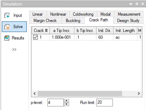
After defining the model domain, locating the crack objects, and assigning all attributes, you are ready to initiate the Crack Path analysis. Go to the Solve dialog and select the Crack Path tab.
In this interface you will see a list of all crack objects that are currently defined in the model, with the default status set to not active. If you want the crack to actually be included in the analysis, you must check the Active box.
Next supply the crack increment to be added at each end of each crack after each iteration. One or both values may be zero. When a crack has an initial length of zero and if the crack object lies on an external boundary, you should supply a non-zero crack increment for both tips. This is because the direction of growth can only be determined plus or minus 180 degrees. If only one tip is assigned a non-zero length, this tip may immediately grow outside the problem domain. After the first iteration, the crack will grow only inside the domain. If the crack is initially internal, it is not possible to predict which tip will be A and which will be B when starting from zero length crack, so assigning only one tip increment may or may not give the desired result.
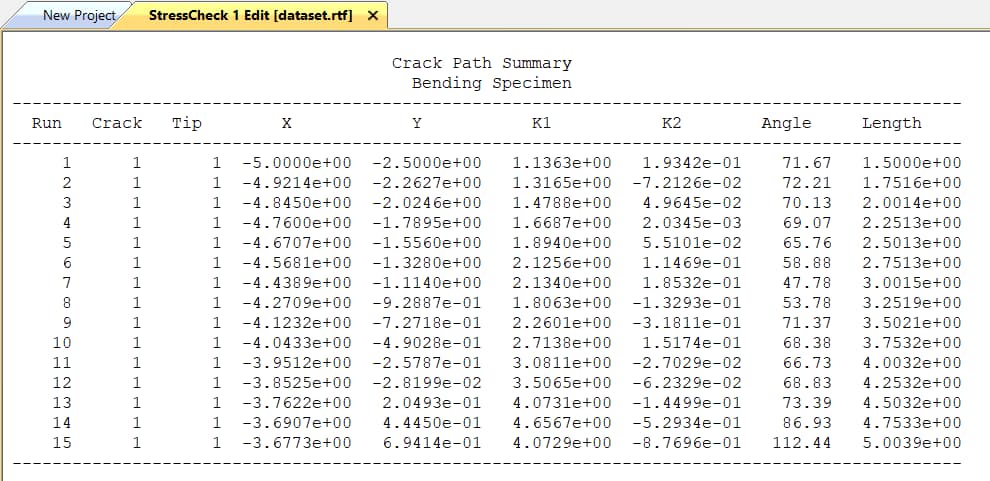
Click the Solve button in Solve dialog to initiate the Crack Path analysis. The Model View will update with each Crack Path analysis iteration, and once the Crack Path analysis is complete a Crack Path Summary of Run #, Crack #, Crack Tip #, X, Y, K1, K2, Current Angle, and Current Length will be reported (Figure 2). The final Crack Path analysis iteration will be also available for post-processing.
The following animation demonstrates an example Crack Path analysis (BendingSpecimenCrackPath.scw in the 2D-Fracture Handbook folder):
NOTE: The Crack Path Summary does not report Theta (θ), instead it reports the angle of the line joining two points (the current crack tip and the previous crack tip point) with respect to the x-axis. Theta is the change in angle between two consecutive crack steps, which StressCheck computes but it does not report.
A few other guidelines are important:
1. Since the fracture mechanics extraction methods are only valid for isotropic materials, and in regions of constant thickness, there may be situations in which K1 and K2 cannot be computed. In this case, the crack may stop growing.
2. When a crack gets close to an external boundary, such that the default contour radius used to compute K1 and K2 goes outside the problem domain, the radius will automatically be reduced in an effort to complete the computation successfully. Similarly, if the crack reaches boundary in the model where there is a material or thickness transition, the radius will also be reduced automatically in order to stay within a region of constant material and thickness. When the crack is incremented, it will then cross the boundary so that the crack can continue to grow. If the crack tip location moves outside the domain, the crack will stop growing from that tip.
3. Choosing a crack increment that is too large will result in a crack path that is wavy. To obtain a smoother crack path, choose a smaller crack increment.
4. When there are multiple cracks in the domain, all active cracks with non-zero crack tip increments will grow simultaneously. As each crack reaches its individual maximum crack length, it will stop growing. When all cracks have reached their maximum, or when the run limit is reached, the analysis will stop.
5. If you wish to update crack increment values or make new cracks active during the analysis, you may either run in STEPWISE mode, or set the run limit to a small number of steps. Return to the Crack Path tab and change values as desired, then continue the analysis using the RESTART option.
NOTE: It is not advisable to interrupt a Crack Path analysis using the ABORT feature (Esc key), unless you intend to INITIALIZE prior to the next analysis. Although you can RESTART after an abort, the results obtained from the analysis will be INCORRECT. This is because the abort request may have come at a time after the mesh was regenerated, but before a new solution is computed and therefore the mesh may not match the solution information maintained in the program. Under these circumstances, all extraction operations would be invalid. StressCheck will display a warning message anytime you attempt to post-process a Crack Path solution that was aborted.
6. Choosing INITIALIZE will reset the problem to the original configuration and start the analysis from the beginning.
NOTE: It is possible to force a Crack Path Analysis with fixed crack orientation. To do that, define the parameter _fix_crack_ang and the initial value of the crack orientation will be used during the analysis.
For an example of setting up and executing a crack path analysis for a 3-pt bending specimen, refer to StressCheck Demo: 2D Crack Path Analysis.
 Serving the Numerical Simulation community since 1989

