Tip: Start typing in the input box for immediate search results.Can't find what you're looking for? Submit a support request here.
Cutting Planes Overview
Introduction
To open the Cutting Planes dialog, select Display > Cutting Planes in the Main Menu or click the Cutting Plane icon located in the Display Options toolbar:

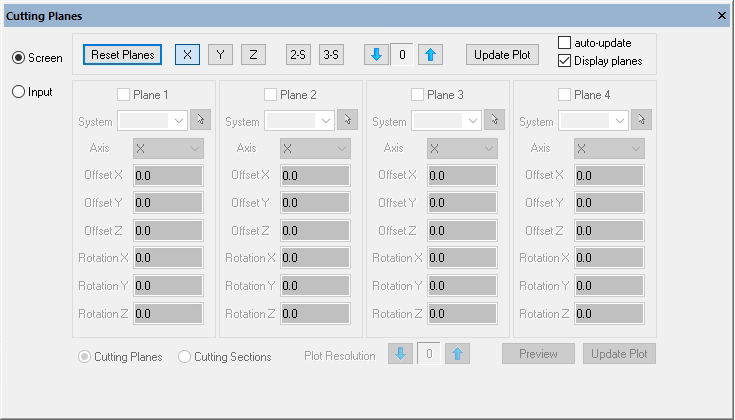
The Cutting Planes dialog (Figure 2) provides the ability to introduce a cutting plane into any model that contains a 3D solid geometric object and/or 3D solid mesh:

For models that contain 3D solid geometry and/or 3D finite element meshes, a surface representing the intersection between the cutting plane and the solid/mesh will be constructed.
By default, cutting plane surfaces will be shown in a transparent grey color with an interactive triad (white axes/grey handles). To disable the display of the cutting plane surfaces and triad, uncheck the “Display planes” checkbox.
Note: closing the Cutting Planes dialog will clear the Model View of cutting planes/cutting sections.
Screen Option

When using the “Screen” option (Figure 3), the cutting plane triad is located at the center of the model and can be used to position and orient each of the three cutting planes. The “X” button activates a cutting plane in the YZ plane, i.e. the X=0 plane. The “Y” button controls the Y=0 plane and the “Z” button controls the Z=0 plane. There are also 2-sided and 3-sided cutting sections that may be toggled on and off. Selecting these options will remove any X, Y, or Z toggles. Below, the X toggle was enabled within the “Screen” option (Figure 4):


If the “Display planes” checkbox is enabled, translation and rotation are activated through the cutting plane triad (white axes/grey handles) controlled by using the mouse. Translations will cause all active planes to be translated along the corresponding global axis. Rotation will cause all active planes to be rotated about the corresponding global axis. Inactive cutting planes will not be affected by the rotations or translations.
The Screen option supports the plotting of fringe contours on cutting planes. More information on plotting via cutting planes below.
Input Option

If the “Input” option is selected (Figure 5) the user may pick from up to four coordinate systems located in the model. The systems can be selected from a dropdown list or by selecting on the screen with the mouse icon enabled. The “Axis” dropdown allows the user to select the cutting plane axis while the remaining input boxes allow the user to control the offset and rotation about the selected coordinate system. The “Preview” button is used to preview the cutting plane configuration in the Model View.
Figure 6 shows how multiple cutting planes, defined by two system locations/orientations, were defined via the “Input” option and “Preview” was enabled:


The Input option supports the plotting of fringe contours on cutting planes. More information on plotting via cutting planes below.
Cutting Planes vs. Cutting Sections
The default “Cutting Planes” option results in the cutting planes removing from view everything that is “in front” of the plane. If more than one cutting plane exists, the resultant visible part is formed by the intersection of the visible parts from each cutting plane. For example, if two planes intersect, then a “wedge” is left visible. When two or more cutting planes are present, the “Cutting Sections” option causes the cutting planes to behave in the opposite way, by keeping in view what is “behind” the plane and displaying the union of the parts that are visible for each cutting plane.
Fringe Plots on Cutting Planes/Sections
If a fringe (contour) plot is created, a fringe plot will be displayed on the cutting plane/section surfaces. The resolution of the results may be increased or decreased by pressing the up/down arrows and the resulting plot can be updated automatically by selecting the “auto-update” checkbox or manually pressing “Update Plot”. Note that changing the fringe plot function and pressing “Plot” within the Results dialog Plot tab will also update the cutting plane plot.
*IMPORTANT NOTE* The Plot Resolution does not correspond to midsides in the cutting plane tool. It is highly recommended the user slowly increment the plotting resolution if the initial results are not satisfactory. Values greater than 4 for the resolution can result in significant plotting times. Pressing “Esc” will cancel the plotting operation.
For an example of how a cutting plane is used to detect multi-body contact penetration, refer to StressCheck Tutorial: Detecting and Correcting Multi-Body Contact Penetration.
 Serving the Numerical Simulation community since 1989
