StressCheck Help Documentation
Tip: Start typing in the input box for immediate search results.Can't find what you're looking for? Submit a support request here.
Display Options Toolbar Overview
Introduction
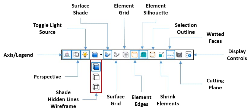
The View > Toolbars > Display Options Toolbar provides icons for better visualization of your model, including perspective, wetted faces, shrink elements, and rendering options. Additionally, an option to render cutting planes is provided. Brief descriptions of commonly used Display Options Toolbar icons are shown in Figure 1:
- The Axis/Legend icon will show/hide the global triad and plot legends, respectively.
- The Perspective icon will display the model in/out of perspective, respectively.
- The Wireframe, Hidden Lines or Shade (default) icons, accessible by clicking the down arrow next to the currently displayed icon, will display the model in wireframe, hidden lines (no transparency), or shaded mode, respectively.
- The Surface Shade icon will draw geometric surfaces with/without shading, respectively.
- The Surface Grid icon will draw geometric surfaces with/without grid handles, respectively.
- The Element Grid icon will draw element faces with/without grid handles, respectively.
- The Element Edges icon will show/hide the element edges, respectively.
- The Element Silhouette icon will enable/disable silhouette outlines on element boundaries (see Display Controls for more information).
- Note: When the Silhouette option is enabled in conjunction with element transparency, objects such as Points, Nodes, Systems, Curves, and Element Edges that are visually obscured by transparent elements will display a silhouette outline. Disabling either the Silhouette option or the display of these objects will remove the silhouette effect.
- Enabling the Selection Outline icon will highlight the outer boundaries of a selected object, including obscured boundaries.
- The Shrink Elements icon will scale/not scale the element display by a “shrink factor” (default is 0.7, or 70% scale; see Display Controls for changing the default).
- The Wetted Faces icon will display wetted element faces/all element faces.
- Wetted element faces represent the “exposed” element faces in the model; internal element faces are not displayed.
- Note: displaying all element faces requires more computational resources for mesh rendering, fringe plotting, etc.
- Clicking the Cutting Plane icon will display the Cutting Plane pane (Figure 2). The Cutting Plane pane provides the ability to introduce a cutting plane into any model that contains a 3D solid geometric object and/or mesh.
- For models that contain a 3D finite element mesh and/or 3D solid geometry, a surface representing the intersection between the cutting plane and the solid mesh/geometry will be constructed.
- If a fringe (contour) plot is created, a fringe plot will be displayed on the cutting plane surfaces. The fringe plot may be updated by clicking the Update Plot button, and the plot resolution increased/decreased by clicking the blue up/down arrows.
- For more detail refer to the Cutting Planes Overview.

- Clicking the Display Controls icon will produce the Display Controls pane.
- The Display Controls pane contains options for controlling geometry and element resolution, geometry and mesh transparency, display formatting, and small feature suppression.
- For more details, refer to the Display Controls section of Display Menu Overview.
 Serving the Numerical Simulation community since 1989

