Tip: Start typing in the input box for immediate search results.Can't find what you're looking for? Submit a support request here.
Edit Menu Overview
Introduction
The following sections provide a brief summary of the options found in the Edit pulldown menu (Figure 1).
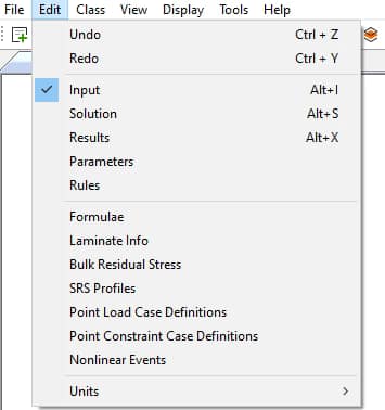
Undo
Use this option to reverse the effect of the previous data transaction. The Undo applies only to creation, deletion, and modification of geometric objects, and other input records. It does not apply to selection, hiding, rotation, or other display related operations.
The Undo operation may be repeated indefinitely until the entire sequence of input operations is reversed. Note: Solution data is not preserved after an Undo operation.
Redo
Use this option to re-apply a data transaction which has been reversed with the Undo operation. Like the Undo, Redo applies only to creation, deletion, and modification of geometric objects and other similar input records.
The Redo may be repeated until all Undo operations have been reapplied.
Note that both Undo and Redo operations are logged in the Project and Message Logs to inform the user of the success of the undo/redo operation, respectively.
Input

The Input option enables the display of the Input dialog within the Simulation pane (Figure 2). There, the user may access the various input classes, including Geometry, Mesh, Thickness, Materials, Loads, Constraints, Solution ID’s, Sets and Parts. A complete description of the Input option is given in the Model Inputs Overview.
Solution
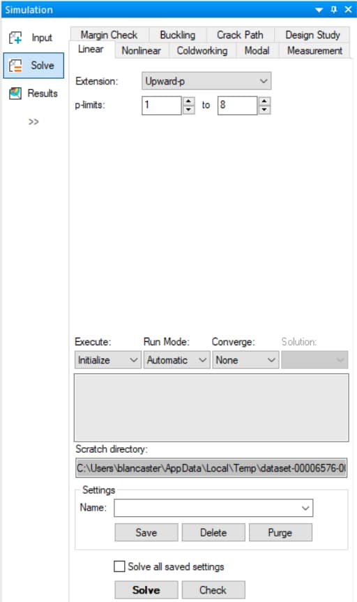
The Solution option enables the display of the Solve dialog within the Simulation pane (Figure 3). There, the user may access the various StressCheck solver options, including Linear, Nonlinear, Modal, Buckling, Margin Check, and Design Study analyses.
Once you have entered the required information for the desired solver, click the Solve button to activate the corresponding solution procedure. A complete description of the Solve option is given in the Solvers Overview.
Results
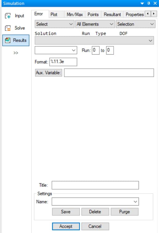
The Results option enables the display of the Results dialog in the Simulation pane (Figure 4). There, the user may access various output and extraction classes, including Error Estimation, Plot, Min/Max, Points, Resultant, Properties, and Fracture Mechanics. A complete description of the Results option is given in the Results Overview.
Parameters
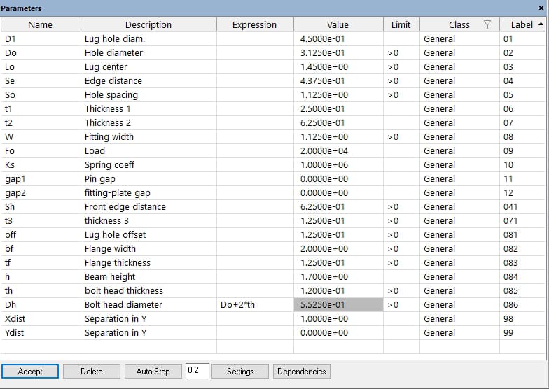
The Parameters option enables the display of the Parameters pane (Figure 5). When selected, entering and editing of alphanumeric parameter definitions may be performed. Parameter definitions may be constants or expressions. A complete description is given in the Parameters & Rules Overview.
Rules

The Rules option enables the display of the Rules pane (Figure 6). When selected, the specification of parameter design rules may be performed. A complete description is given in the Parameters & Rules Overview.
Formulae
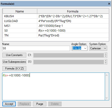
The Formulae enables the display of the Formulae pane for entering and editing formula record definitions (Figure 7). Formulae may be used in both pre- and post-processing. A complete description is given in the Formula Overview.
Laminate Info
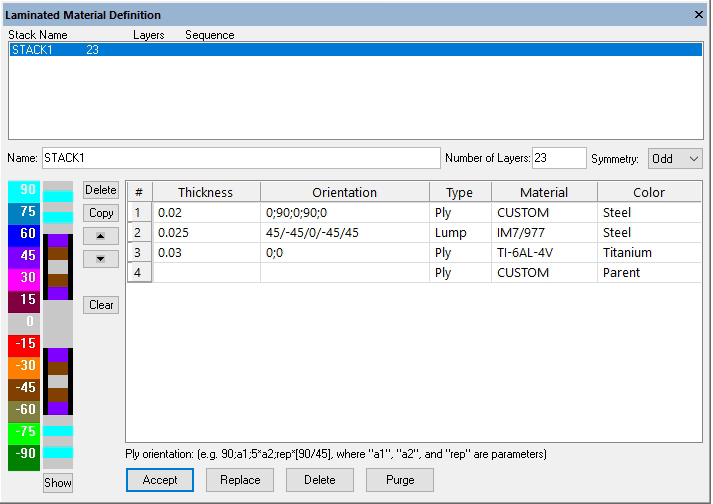
The layout of the Laminated Material Definition dialog is designed to facilitate the description of a parametric laminate stack, to display visual feedback of the material attributes for each ply, and to automatically assign material properties to the child mesh based on attributes described in the stack description (Figure 8).
Before defining a stack record, at least one laminate orthotropic or laminate isotropic material record must be defined. A complete description is given in Automatic Laminate Builder.
Bulk Residual Stress
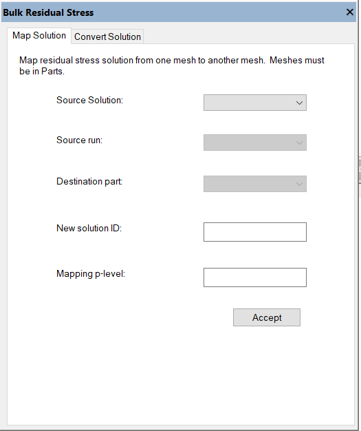
The Bulk Residual Stress (BRS) window may be activated in order to provide a module for including BRS in linear analysis (Figure 9). A complete description is given in the Bulk Residual Stress (BRS) Overview.
SRS Profiles

The Subsurface Residual Stress (SRS) Profile window may be activated to input information regarding the subsurface residual stress distribution for predicting the resulting distortion (Figure 10). A complete description is given in the Subsurface Residual Stress (SRS) Overview.
Point Load Info
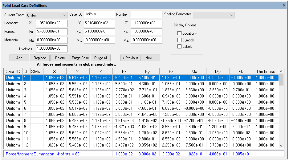
A capability to import point load information (Total Loads At a Point, or TLAPs, and forces/moments per unit length) from a global model into StressCheck can be accessed by using Edit > Point Load Info from the Edit pulldown (Figure 11). The dialog enables the modification of existing input data or the creation of new point load objects.
The first column in the Point Load Case Definitions dialog indicates the case ID, the second is the object number, and the third column (Status) is used for indicating whether the point load object has been assigned to a load ID and the number of times it has been used. Columns 4 to 6 contain the global coordinates of the point load record (X, Y, Z), while columns 7 to 12 contain the three forces (Fx, Fy, Fz) and three moments (Mx, My, Mz). The last column shows the shell thickness used in the global model. Display options are available for visualization of point load records, and an option to scale point load records via a parameter may be utilized. A complete description is given in the Global Local Analysis Overview, Point Running Loads Implementation and Total Load at a Point (TLAP) Implementation.
Point Constraint Info
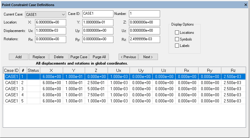
A capability to import displacements and rotations obtained from the solution of a global shell model into StressCheck can be accessed by using Edit > Point Constraint Info from the Edit pulldown (Figure 12). Once the point constraint information is imported into StressCheck and the local model is available, the user selects the Constraint tab of the Input dialog to assign a set of point constraint objects to a group of faces of the local model.
The Point Constraint Case Definitions dialog enables modifying existing input data or creating new point constraint objects. The first column in the table is the case ID, the second is the object number, and the third column (Status) is used for indicating whether the point constraint object has been assigned to a constraint case and the number of times it has been used. Columns 4 to 6 contain the global coordinates of the point constraint record (X, Y, Z), while columns 7 to 12 contain the three displacements (Ux, Uy, Uz) and three rotations (Rx, Ry, Rz). Display options are available for visualization of point constraint records. A complete description is given in the Global Local Analysis Overview and Point Displacements/Rotations Implementation.
Nonlinear Events
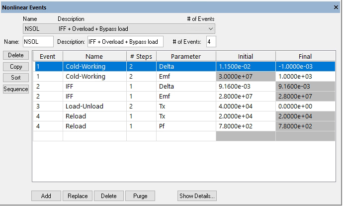
When solving a problem using incremental plasticity, you might need to create, add, and/or edit the nonlinear events to be solved (Figure 13). The Nonlinear Events dialog is accessible using Edit > Nonlinear Events from the Edit pulldown. A complete description is given in the Nonlinear Events Overview.
Units
This option provides access to manually select the system of units. You may change the system of units only if no geometry has yet been defined. If you have an existing model that is not Parasolid based (no CAD geometry was imported), you may insert a record into the *.sci file that will assign the units.
 Serving the Numerical Simulation community since 1989
