Tip: Start typing in the input box for immediate search results.Can't find what you're looking for? Submit a support request here.
Failure Criteria Option
To analyze damage initiation in the polymer of a composite material and in bonded composite joints, strain invariant failure criteria have been proposed in the literature. It has been shown that damage initiation can be correlated with the volumetric and equivalent strains of the lamina which are functions of the strain invariants. The strain invariants depend on the three principal strains and include the effects of mechanical loads and environmental contributions.
Basic Equations
The volumetric strain, the equivalent strain, and related quantities are defined as follows:

where ϵeq is the equivalent strain, ϵ1, ϵ2, ϵ3 are the principal strains, and Ji are the invariants of the strain tensor:

Often the strains due to the combined effect of mechanical and thermal loads must be computed, but these loads cannot be applied simultaneously to the component because different constraint conditions are required for each type of load. A procedure to combine these solutions is then required to compute the quantities of interest.
The principal strains and strain invariants are computed from the directional strains obtained from the finite element solution. To properly account for the effects of mechanical and thermal loads, separate finite element solutions are typically required because the constraint conditions for the mechanical loads may be different from those for the thermal loads. Therefore, the procedure implemented in StressCheck allows the user to compute strains by combining any two solutions with the same or different number of degrees of freedom. Additionally, a facility was added for incorporating arbitrary multiplying or additive factors for each solution and a global additive factor.
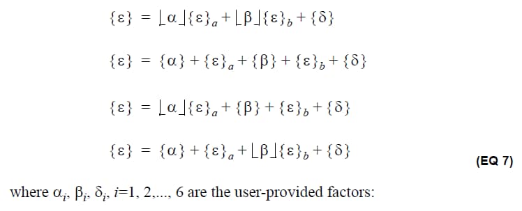
Let {ϵ}a represent the strain tensor at a point obtained from the finite element solution corresponding to the applied mechanical loads, and let {ϵ}b be the strain tensor at the same point obtained from the finite element solution corresponding to the thermal loads. One of four combined strain tensor {ϵ} can be extracted, using user-provided factors as follows:


Other functions can be computed based on the combined strain tensor, such as the equivalent strain, the strain invariants, and formula-based expressions utilizing the combined strain tensor components. The combined strain tensor contains six directional components according to the following convention:

where x, y, z, represent the strain directions in a global or local Cartesian coordinate system; r, θ, z are the strain directions in a cylindrical coordinate system; and 1-2-3 refer to the strain directions in the material coordinate system (applicable to orthotropic and laminate materials). Which one of these strain tensors is computed depends on the coordinate system selection in the Results pane.
Failure Criteria Interface
The Failure Criteria option of the Calculator function is accessible from the Plot, Points and Min/Max extractions as shown in Figure 1. This interface is activated whenever the Calc. function is selected from any of these post-processing classes, and the Failure Criteria tab of the StressCheck Calculator is selected:

The Failure Criteria tab with the Input subtab, contains the following fields:
Solution ID Activation Buttons
They can be turned on and off to activate or deactivate the contribution from a particular solution to the requested strain function. At least one button must be on.
Solution ID and Run #
Selection of the solution ID and run number from the set of existing finite element solutions that will be used to compute the combined strain-related quantities. If zero is entered as a run number, then it is possible to get convergence results based on the run settings in the corresponding Results tab (Points or Min/Max).
Extraction Functions
List of strains and strain-related functions that can be computed by combining the selected solutions with the user-provided factors. They include all six directional strain components (ϵx, ϵy, ϵz, γxy, γyz, γzx), the three principal strains (ϵ1, ϵ2, ϵ3), the equivalent strain (ϵeq), the strain invariants (J1, J2, J3) and a formula option (Fmla).
When the Formula option is selected, then the formula field is enabled and the user can enter an expression in the corresponding field. Any expression containing intrinsic functions and logical relations among the listed functions can be entered. The formula expression can be up to 119 characters long. For a complete list of intrinsic functions supported by StressCheck, refer to What Intrinsic Functions and Mathematical Expressions Are Supported in StressCheck?
When computing directional strains, they can be in the global system, in a local Cartesian or cylindrical system, or in the material directions, depending on the system selection in the Results interface (see Figure 1). It is understood that if a listed strain component is requested in a local system, the contributions from SOL1 and SOL2 are computed in the same system.
If the Average button for the Points extraction is turned on, then the selected functions will be computed as average (in the integral sense) over the selected edge, face or element.
By toggling the Et/Em button in any of the Results interfaces, the selected strain function can be computed based on total (Et) or mechanical (Em) strains.
The number of functions that can be selected depends on the Results tab. From the Plot and Min/Max tabs, only one function at the time can be selected for extraction. From the Points tab any number of functions can be selected at the same time.
Factors and Operation Selectors
Input fields to enter the factors to be used for each solution in the context of Eq. 7. The factors can be constants or previously defined parameter names. The toggle switch under each column controls whether the factors are multiplied or added to the strains computed from each solution. Add or Multiply applies for α and β factors only; the δ factors are always additive. The sample expression located under the Add/Multiply buttons is adjusted based on the setting of the operation selectors to help the user understand the use of the factors as indicated by Eq. 7.
A total of 18 factors can be input in three columns. The first and second columns are associated with SOL1 and SOL2, while the third column is always additive. Each factor is added or multiplied to the strain component listed on the left.
Settings Subtab
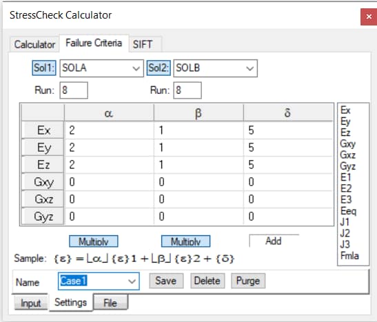
The Settings subtab located at the bottom of the form is used for saving/retrieving the input factors α, β and δ in the current StressCheck session and in the StressCheck project file. The interface is shown in Figure 2.

To save a set of input factors, simply enter the name in the corresponding field and click on the Save button. To retrieve a previously saved setting, simply click on the down arrow key and select from the list of available names. The Delete button can be used to remove the saved input associated with the selected name. The Purge button will remove all the saved settings from the database.
File Subtab
The File subtab is used for saving/retrieving the input factors α, β and δ in a neutral (ASCII) file with the extension FAC. The interface is shown in Figure 3.

To save a set of input factors to a file, type the name of the file in the input field and click on the Write button. The file will be placed in the same directory as the current StressCheck session. To select a different directory, click on the Browse button first to select the location for the file. To retrieve a previously saved file, click on the Browse button to select the file and then click on the Read button.
Results
The combined strains are reported in Chart/Table form when the extraction is performed from the Points and Min/Max Results tab or in contour fringes when extracted from the Plot tab. Each function extracted from the Failure Criteria tab of the Calculator interface is identified by the prefix FC as shown in Figure 4:


The figure shows the Graph output from the Points extraction interface in which the Failure Criteria functions Ez (ϵz), Eq (ϵeq) and J1 (J1) were requested at several points. Note that each function has the prefix FC- before the name in the legend of the graph and in the column heading of the table. The solution ID and run # included in the titles are the ones selected in the Points interface.
The same prefix is used to identify the selected function from the Plot Results tab as indicated in Figure 5:

In this case, the Failure Criteria function Ez is identified in the legend as FC-Ez. The solution ID and run # included in the legend are the ones selected in the Plot interface.
 Serving the Numerical Simulation community since 1989
