Tip: Start typing in the input box for immediate search results.Can't find what you're looking for? Submit a support request here.
Fastened Connection Analysis Overview
Introduction
StressCheck provides an advanced capability which allows for the computation of both the structural and the strength responses of fastened structural connections. This capability is available in the Planar reference only.
The implementation accounts for the following:
- Partial contact between fastener and plate,
- Fastener shear stiffness,
- Material and geometric nonlinearities,
- Interference fitting,
- Initial clearance between fastener and plates,
under the assumption that the effects of bending are negligible and there is no friction between the contact surfaces. In other words, all dominant effects in frictionless shear connections are accounted for in a two-dimensional setting.
Fastener Element
Theory and Derivation
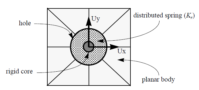
The main component of the implementation is a special fastener element which consists of a rigid core with two degrees of freedom (Ux, Uy) connected to the planar body by a distributed radial (normal) spring as illustrated in the following:

The spring coefficient (Kr) is determined from the elastic solution of a disc under radial compression (plane-strain condition), as the ratio between the applied pressure and the radial displacement. The expression for the spring stiffness, evaluated by StressCheck automatically, is:

where E and ν are the modulus of elasticity and Poisson’s ratio of the fastener material, and D is the diameter of the hole. The full derivation of the fastener element’s radial stiffness Kr from an elastic disc of outer radius ro and inner radius ri is as follows:
 Loading…
For more information on using the fastener element, refer to What is Required in a Fastener Element Analysis?
Creating Fastener Elements
To create one or more fastener elements in a Planar model, ensure the display of curves is enabled and locate the circular curve in which a fastener element will be inserted. Set the C/A/O/M to Mesh tab > Create > Fastener > Selection, and then left-click on the circular curve. A brown-colored fastener element will fill the circular curve. This process may be repeated for any circular curve in the model.
Assigning Materials to Fastener Elements
Fastener elements may be assigned linear isotropic materials only (Plane Stress or Plane Strain). To assign one or more fastener elements a linear isotropic material definition, set the C/A/O/M to Material tab > Assign subtab > Select > Fastener > Selection, and select one or more fastener elements. Then, specify the material ID in the “ID:” drop-down and if desired, specify a color for the assignment. Finally, click Accept to assign the material ID to the fastener element(s).
Loading & Constraining Fastener Elements
- The rigid core of a fastener can be connected directly to the rigid core of other fasteners (Constraint tab, set A/O/M to Select > Fastener > Connection) or using a link element (Mesh tab, set A/O/M to Create > Link > Connection).
- The rigid core of a fastener can be fixed in one or both directions (Constraint tab, set A/O/M to Select > Fastener > Displacement, set X and/or Y to zero).
- The rigid core of a fastener can be loaded by a force (Load tab, set A/O/M to Select > Fastener > Force Load) or an imposed displacement (Constraint tab, set A/O/M to Select > Fastener > Displacement).
- Interference fitting or initial clearance can be specified also for each fastener element (Load tab, set A/O/M to Select > Fastener > Interference, enter a diametral interference). This makes it possible to assign clearance or interference fitting at each connecting plate location independently.
- If two plates are connected by a fastener, for example, interference fitting can be specified for the part of the fastener going through one of the plates and neat fit can be assigned to the part of the fastener going through the other plate, or any other combination of neat fit, interference fitting or initial clearance.
For an example of fastener element usage, refer to StressCheck Tutorial: Fastener Element and General Nonlinear Analysis.
Link Element
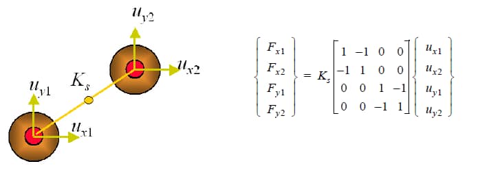
When a link element is used for connecting two fastener elements (Mesh tab, set A/O/M to Create > Link > Connection, then select two fastener elements at the same global XY location to automatically generate the Link element), the force-displacement relation between the connected fasteners becomes:

where Ks is the spring stiffness of the link, in force per unit length, given under the material definition tab of the model input interface.
If fasteners on a plane of symmetry are linked to other fasteners on a plane of symmetry, then the link stiffness value should be half the value that would be used for linked full fasteners.
The link element allows incorporation of the shear/bending stiffness of the fastener into the model independent of the radial (propping) stiffness of the shank. The radial stiffness is taken into consideration by the spring stiffness Kr of the fastener.
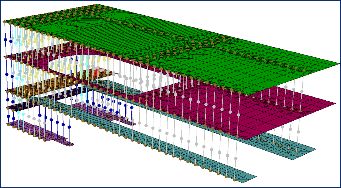
For an example of link usage in fastened connection analysis, refer to StressCheck Demo: 2D Fastened Joint Analysis.
Executing a Fastened Connection Analysis
The analysis of a fastened structural connection requires two steps:
- First, a linear analysis is performed using p-extension to assess the quality of the numerical solution.
- Second, a general nonlinear (NL Gen) analysis is performed to account for all nonlinear effects present in the connection (contact, clearance, geometric and material nonlinearities).
Therefore, to perform a fastener analysis follow the same procedure described for the execution of a general nonlinear analysis. Note: A quadrilateral or triangular element can have only one edge connected to a fastener element.
For a tutorial on the typical steps for analyzing a fastened connection analysis, refer to StressCheck Tutorial: Planar Modeling of a Skin-Stiffener-Fasteners Assembly.
Resultant Extractions for Fastener Elements
The resultant (reaction) for one or more fastener elements can be computed through the Resultant tab of the Results dialog by setting the A/O/M combo to Select > Fastener > Selection, and selecting one or more fastener elements from the modeling viewing window. The Resultant tab will report the total forces/moments for all selected fasteners.
- If one fastener is selected, a graph window will appear to report the fastener resultant summary for each run.
- If multiple fasteners are selected, two graph windows will appear: one with a tabular output of each fastener resultant for each run, allowing the user to determine fastener load transfer by fastener ID #, and one with a summary for all fasteners for each run.
Note: the Fastener object is only available in the Planar reference. Linear solution fastener resultants are only meaningful for convergence checking.
 Serving the Numerical Simulation community since 1989

