Tip: Start typing in the input box for immediate search results.Can't find what you're looking for? Submit a support request here.
Fracture Mechanics Analysis Overview
Introduction
This article describes the procedures for computing the stress intensity factors and the T-stress in linear elastic fracture mechanics for two- and three-dimensional linear problems with isotropic materials; the computation of the separated J-integral for two- and three-dimensional linear problems with isotropic, orthotropic or laminate materials; and the computation of the J-integral in elastic-plastic fracture mechanics for planar and axisymmetric problems.
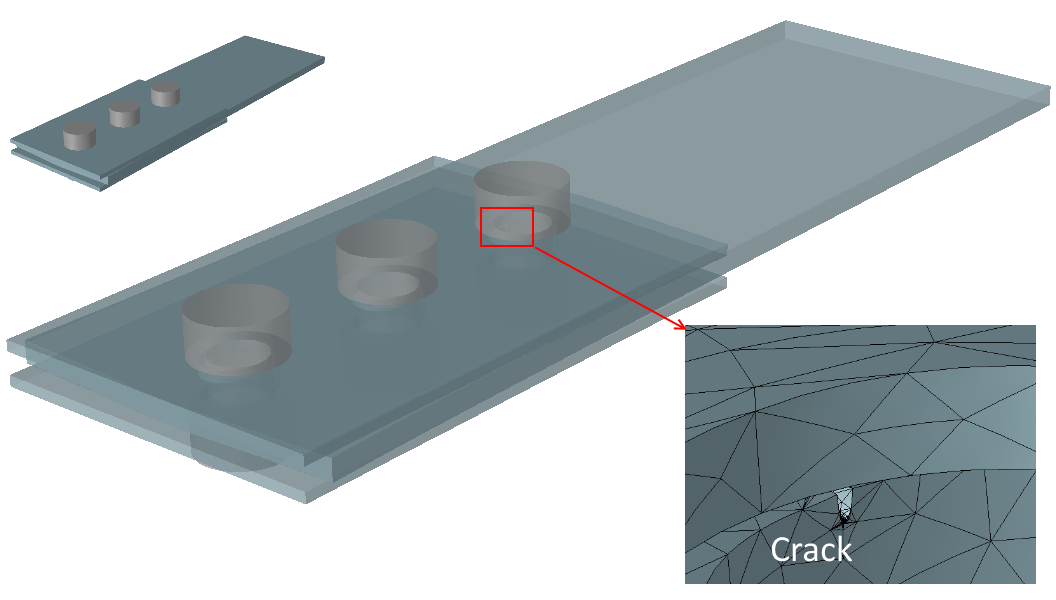
The implementation supports thru-cracks in Planar and thru-cracks/part-thru cracks in 3D. Additionally, the computation of fracture mechanics parameters in the presence of loaded crack faces (via CIM-LC) and residual stresses (via J-Integral) is described.
You should be familiar with the procedures for creating a finite element mesh for Planar, axisymmetric and 3D problems and executing a linear analysis. You should also be familiar with nonlinear analysis if elastic-plastic computation is of interest.
For more background on the computation of fracture mechanics parameters via numerical simulation, refer to Numerical Simulation Series: Fracture Mechanics Parameters.
Computing Stress Intensity Factors (SIFs)
StressCheck has an advanced method implemented for the computation of Mode 1 (i.e., K1), Mode 2 (i.e., K2) and Mode 3 (i.e., K3) stress intensity factors (SIFs) in linear elastic fracture mechanics. SIFs are reported in units of F/L2 * √(L).
The method is superconvergent. This means that the error in SIFs converges to zero much faster than the error in energy norm as the number of degrees of freedom is increased, provided that the number of degrees of freedom is sufficiently large; therefore the quality of the solution is assessed based on the convergence of K1/K2/K3 rather than in energy norm.
- For information on extracting crack tip or single-click SIFs via the Fracture tab in the Results dialog, refer to Fracture Mechanics Overview.
- For information on extracting 3D SIF distributions via the Points tab in the Results dialog, refer to Extract Points Overview.
There is an important practical benefit to StressCheck’s implementation of SIF computation: the mesh does not have to be overly refined at the crack tip/front, and the polynomial degree does not have to be high to obtain accurate results. It is simply recommended to use two (2) layers of refinement about the crack tip/front, with the remainder of the domain meshed using minimal refinement. For more details on optimal fracture mechanics meshing strategies, refer to Fracture Mechanics Meshing Strategies.
The method used to compute SIFs, called the Contour Integral Method (CIM), is described in Numerical Simulation Series: Fracture Mechanics Parameters under Stress Intensity Factors. The SIFs can be computed for the linear solution of isotropic materials in the absence of body forces and thermal loading, and with traction free crack faces (see CIM-LC below for the computation of SIFs for loaded crack faces). For axisymmetric problems, the stress intensity factor depends on the radius of the integration path (r). However, as r→0 the contour integral becomes path-independent.
Numerical studies (“Numerical Analysis of Singularities. Part 2: Computation of Generalized Flux/Stress Intensity Factors.” by Szabo, B. A. and Yosibash, Z. from International Journal for Numerical Methods in Engineering, Vol. 39, 409-434, 1996.) indicated that for r/rc < 0.1, the values of the stress intensity factors are practically independent of r (rc = crack tip location).
A Note About the CIM in 2D (Planar)

The stress intensity factors K1 and K2 are computed using a path-independent superconvergent extraction by the contour integral method (CIM) over a circular path around the crack tip. The main advantage of this implementation is that simply selecting a radius for the circle which defines the integration path and pointing to the crack tip with the cursor, accurate results and fast convergence are obtained, even with coarse meshes. Note: in theory the radius of the circular path is arbitrary but the path must lie inside the solution domain.
A Note About the CIM in 3D
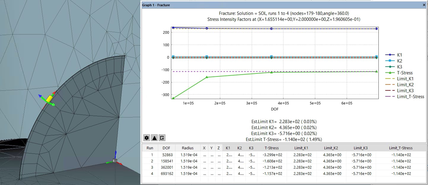
In 2D (Planar) elasticity, the computation of the stress intensity factors by the contour integral method (CIM) is path independent (i.e., independent of the size of the radius of integration). When the contour integral is computed using the displacement and stress fields from a numerical approximation of the solution, there is a small influence of the radius of integration due to numerical errors (both from the approximation of the solution and the numerical integration).
The reason for using layers of refinement graded in geometric progression towards the singular point is to distribute the error evenly on the elements in the vicinity of the crack tip. The characteristic size of the refinement denoted by “a” is typically determined from the geometry surrounding the crack tip.
The stress intensity factors K1, K2 and K3 are computed using superconvergent extraction by the CIM over a circular path around the crack front. The procedure implemented in StressCheck determines a cutting plane normal to the tangent to the crack edge at the pick point and extracts the global components of the stresses and displacements along a circular path contained in the cutting plane. These stresses and displacements are projected into the cutting plane and integrated with the extraction function to compute the CIM as discussed in Numerical Simulation Series: Fracture Mechanics Parameters.
In general for 3D crack problems the contour integral is not path-independent, in particular for curved crack fronts. When extracting stress intensity factors (SIFs) in a 3D stress field for a curved crack at a given point along the front, the radius of integration includes the effect of adjacent points, in other words the extraction is affected by neighboring points. The reason is that the eigenfunctions associated with the stress intensity factors are not orthogonal to each other as is the 2D case. Using an integration radius as small as possible will decrease the influence of adjacent points when computing the SIFs.
The computation of the stress intensity factors in 3D by the contour integral method must be evaluated in the limit when the radius of integration goes to zero. In practice using a sufficiently small radius of integration, inside the region where the approximation of the solution is good, is enough to obtain accurate results. Since in a typical mesh the inner-most layer of elements includes the crack front, the integration path should run outside this inner-most layer of elements to avoid the effect of the singularity on the numerical solution. Ideally, the radius should be the smallest possible radius outside the first layer of refinement.
The refinement depends on the characteristic length “a”, and the radius used for extraction is typically expressed as a function of “a” as well. For example, if two layers of refinement are used, the radius of the inner most layer would be Ri = 0.152*a = 0.0225*a, so that the integration radius (R) should be larger than 0.0225*a (i.e., R > Ri).
Numerical evidence suggests that an integration radius in the range R/a = 0.025 – 0.030 is enough to obtain accurate results. The values of SIFs computed within this interval are accurate enough for engineering analysis. If more accuracy is required, then extrapolation to a zero radius should be considered. For more information on the computation of 3D SIF’s, refer to Computation of SIFs in StressCheck.
For an example of single-click SIFs via the Fracture tab and SIF distributions via the Points tab for a 3D cracked stiffened lug, refer to StressCheck Demo: Part-Thru Crack SIFs for Stiffened Lug.
CIM with a Loaded Crack Face (CIM-LC)
The mode I SIF (KI,RS) due to residual stress or KI due to a mechanical loading combined with residual stress can be computed with the contour integral method (CIM) with a loaded crack (CIM-LC). This is the fastest extraction technique for computing SIFs available in StressCheck. The method involves loading the crack face with a traction representing the residual stress distribution at the location of the crack.
Algorithm
The derivation of the CIM presented in “Finite Element Analysis” by Szabó, B. A. and Babuska, I., John Wiley and Sons, Inc.
New York, 1991 and “Computation of the amplitude of stress singular terms for cracks and reentrant corners” by B. Szabó and I. Babuška, Fracture Mechanics: Nineteenth Symposium ASTM STP 969, Philadelphia, 1988 is based on the assumption that the crack faces are stress-free. This restriction was removed in “The contour integral method for loaded cracks” by J. P. Pereira and C. A. Duarte, Communications in Numerical Methods in Engineering, vol. 22, no. 5, pp. 421-432, 2006.
When the crack faces are loaded, the mode I SIF is computed using the CIM-LC as follows:

In reference to the boundaries labeled below:
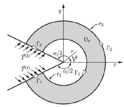
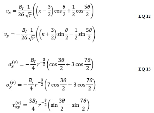
The extraction functions in EQ 11 are:
To account for the presence of residual stresses, boundaries Γ3 and Γ4 are loaded with the normal tractions representing the residual stress field on the faces of the crack. The contribution to KI from these boundaries can be expressed as a simple summation:

Where are the coefficients ai of a polynomial expansion of the crack face traction in the extraction plane normal to the crack front:

When KI is extracted using CIM-LC, the formula representing the normal residual stress component is expanded as a polynomial traction in the local crack coordinate system and the integration is quickly performed using equation (EQ 14). It is assumed that the contributions to KI from boundaries Γ3 and Γ4 are identical.
CIM-LC vs. J-Integral
In comparison to SIF extractions via the J-Integral (discussed below in Computing the J-integral), the CIM-LC has three advantages:
- Faster solution times when tractions are defined on crack faces instead of volumetric residual stresses over the cracked component.
- For most practical applications only one RS component is needed (normal to the crack face) to compute SIFs with the CIM-LC. For the J to K approach, the full RS tensor is needed (refer to the J-integral algorithm section of this article for explanations of RS fields).
- The extraction of CIM-LC is faster than the J-integral.
Loading the Crack Face
To input residual stresses (RS) on a crack face simply define a traction load on the crack face where the normal component of the traction is given by a StressCheck formula, and include that load in the solution load case. Then, when extracting SIFs, StressCheck will automatically detect the face load and use the CIM-LC technique. The formula will be evaluated with respect to the chosen system in a Cartesian or cylindrical sense depending on the System Option saved with the formula.
Note that compressive residual stresses should be applied as a positive normal traction and tensile residual stresses should be applied as a negative normal traction. This is opposite from typical stress sign convention where positive indicates tension inside a body. But consider that applying a compressive residual stress load as a compressive normal traction to the crack face will tend to open the crack, producing the opposite of the desired response. Therefore, apply a compressive residual stress as a tensile crack face load which will tend to close the crack (or bring the crack faces closer together).
Computed SIFs will include the superposition of both the residual stress SIF (due to the loaded crack face) and mechanical SIF (due to remote loading). All standard procedures for fracture post-processing apply for CIM-LC extraction (extract just outside the innermost layer of elements, check convergence, etc.).
For an example of CIM-LC, refer to StressCheck Tutorial: Modeling and SIF Extraction for a 3D Loaded Crack Face.
Computing the J-Integral
The computation of the energy release rate has been used for many years to determine the onset of crack propagation. In recent years, the use of composite materials has become common practice in the aerospace industry and correlating the energy release rate with crack propagation, originally developed for isotropic materials in a 2D setting, is now been extended to structures made of laminated composites.
For most cases of interest, the energy release rate has to be computed in a three dimensional setting for bi-material crack interfaces and orthotropic material properties. Moreover, given the typical complexity of the displacement and stress fields associated with composite materials, the analysis requires the computation of the energy release rate components associated with each failure mode (i.e., Modes I, II and III).
Several theories are available to compute the energy release rate component, among them: the Crack Closure Technique (CCT), the Virtual Crack Closure Technique (VCCT), and the J-integral decomposition. The implementation of the J-integral decomposition in StressCheck was selected as the mechanism to accurately determine the energy release rate components J1, J2 and/or J3. The J-integral is computed along a circular path around the crack tip as described under the J-integral section of Numerical Simulation Series: Fracture Mechanics Parameters.
The implementation of the J-integral decomposition in StressCheck is limited to linear solutions of isotropic and orthotropic/laminate materials in 2D and 3D in the absence of body forces and thermal loads and with traction-free crack surfaces. Two extraction procedures are available:
- For a single point extraction (Fracture dialog) each component of the J-path (for modes I, II and III) and the symmetric and anti-symmetric components of the J-area are computed. This allows the user to determine the size of the integration path for which the contribution of the J-area to the total J-integral is negligible.
- For multi point extraction (Points dialog) only the J-path components are computed by default. If desired, the user can compute J-area along the crack front by providing an underscore parameter (_JArea). In that case the extraction will provide the symmetric component of J-area (JAS) if J1p is requested and anti-symmetric component (JAAS) if J2p is requested.
For more information on StressCheck’s implementation of the J-integral, refer to J-Integral Decomposition Technical Brief.
Note: the computation J-integral for elastic-plastic solutions of isotropic materials is limited to Planar and Axisymmetric problems. For elastic-plastic solutions, the integration path should be selected in such a way that it does not cut through the plastic zone around the crack tip. The procedures for computing the J-integral decomposition and the J-integral for elastic-plastic solutions will be illustrated in the following.
Computation of SIFs via Separated J-integrals
For linear elasticity, the relationship between the J-integral and the mode I, II and III stress intensity factors can be given by (“On the decomposition of the J-integral for 3D crack problems” by O. Huber, J. Nickel and G. Kuhn, International Journal of Fracture, vol 64, pp. 339-348, 1993, and “Decomposition of the mixed-mode J integral-revisited”, by R.H. Rigby and M.H. Aliabadi, International Journal of Solids and Structures, 35(17):2073-2099, 1998):

From where it can be shown that:


J-Integral with Residual Stresses
The J-integral components JI, JII, and JIII or the SIFs KI, KII, KIII due to residual stress (RS) or due to a mechanical loading combined with residual stress can be computed with the separated J-integral in StressCheck. Unlike the CIM-LC, all six components of the RS tensor must be known and applied as an initial volume load.
Note that the six tensor components must be in equilibrium or they do not represent a RS distribution and the computed fracture mechanics parameters may not represent what is expected.
Algorithm
A path-area independent J-integral algorithm is available in StressCheck for computing the components JI, JII, and JIII for cracks in a RS field. A RS field is a self-equilibrated stress distribution resulting from non-uniform plastic deformations such as those produced by coldworking operations, satisfying the equilibrium equations and the boundary conditions. In the absence of external loads, if the internal strain field does not satisfy the compatibility equations, then an additional mechanical strain field is induced in order to restore compatibility and residual stresses are set up in the body (see S. Timosheno and J. N. Goodier, Theory of Elasticity, 2nd ed., New York:
McGraw-Hill Book Company, 1951). Such residual stress problems can then be treated as initial strain problems.
When initial strains are present the total strain εij in the definition of the J-integral given by EQ 17 must be viewed as the sum of the mechanical strain εmij and initial strain ε0ij (i.e. εij= εmij+ε0ij).

The initial strain remains constant during subsequent deformation and the mechanical strain is related to the stress through the material constitutive law. From “Fracture Mechanics Analysis of a Crack in a Residual Stress Field” by Y. Lei, N. P. O’Dowd and G. A. Webster, International Journal of Fracture, vol. 106, pp. 195-216, 2000 and “Fracture Behavior in the Presence of Thermal Strains” by R. A. Ainsworth, B. K. Neale and R. H. Price, Int. Conf. on Tolerance of Flaws in Pressurized Components, 1987 a path-area independent J-integral equation can be obtained as follows:
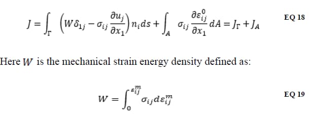
A is the area enclosed by the integration path Γ and A → 0 as Γ shrinks to the crack tip. Implicit in this definition for J is that the initial strains ε0ij are bounded at the crack tip. The area integral correction JA in EQ 18 converges to zero as the size of the integration path approaches zero. Therefore, it is expected that in cases of practical interest the contribution of the area integral will be small enough and it can be neglected, resulting in faster extraction times.
The computation of the area integral requires information that is computationally more expensive to generate than the path integral. However, in order to estimate how close the value of the path integral is to the total integral and therefore provide feedback to the user, the computation of the area integral is available in the Fracture tab of the Results dialog.
The implementation accounts for the computation of the separated J-integrals by separating stress/strain and displacement fields into modes I, II and III respectively, as per “Decomposition of the mixed-mode J integral-revisited” by R.H. Rigby and M.H. Aliabadi, International Journal of Solids and Structures, 35(17):2073-2099, 1998 and “Computing the J-integral,” StressCheck Master Guide, Release 9.2, vol. Advanced Guide Chapter 3, p. 175, 2011.
Once the values of JI, JII, and JIII are determined they are converted to KI, KII, and KIII following the procedure outlined in “On the decomposition of the J-integral for 3D crack problems” by O. Huber, J. Nickel and G. Kuhn, International Journal of Fracture, vol 64, pp. 339-348, 1993, and “Decomposition of the mixed-mode J integral-revisited”, by R.H. Rigby and M.H. Aliabadi, International Journal of Solids and Structures, 35(17):2073-2099, 1998:

- The sign of KI is determined based on the relative displacements of points on the faces of the crack.
- KII and KIII are always reported as positive.
A Note About Converting J to K:
The conversion shown in EQ 20 is valid for linear elastic materials under plane stress or plane strain conditions. For these cases it can be shown that the conversion of J to K produces the same result as directly computing K using the Contour Integral Method (CIM).
However, for 3D part-thru (corner) cracks that are not purely plane stress or strain, the J to K conversion given by EQ 20 produces values of K that may differ from those computed by CIM. Numerical studies have shown that the difference is problem-dependent, but is typically limited to 5% or less.
If all residual stress tensor components are known, this method for computing SIFs has one advantage over the CIM-LC in that it can provide an SIF for each of the three modes of fracture I, II, and III.
Residual Stress Input
As the entire self-equilibrated RS tensor across the entire domain is required to use the J-integral in the presence of RS, the RS must be applied as a volume initial load. There are two techniques available in StressCheck for applying a volumetric RS load: specify a subsurface residual stress (SRS) load or specify a bulk residual stress (BRS) load. Instructions for assigning SRS and BRS loads can be found in Subsurface Residual Stress (SRS) Overview and Bulk Residual Stress (BRS) Overview, respectively.
Often the SRS or BRS loads are specified as formulae in terms of (x,y,z) or (r,t,z). However a StressCheck solution can be used as the input residual stress load as well. For example, the incremental plasticity module could be used to solve for the residual stresses following a coldworking operation. The computed residual stresses could then be converted into a mapped solution and used with a BRS load where Stress Source = Solution. In this way it can be guaranteed that that input residual stress field is in equilibrium (assuming the approximation error in the incremental plasticity solution is small).
Fracture Mechanics Parameters: J-Integral
On the Fracture tab of the Results dialog there are six fracture extraction parameters computed for the energy release rate computed with the J-integral:
- J1p: The mode 1 contribution of the path integral.
- J2p: The mode 2 contribution of the path integral.
- J3p: The mode 3 contribution of the path integral.
- J1a: The symmetric (mode 1) contribution of the area integral.
- Jas: The antisymmetric (modes 2 and 3) contribution of the area integral.
- Jai: The initial strain contribution of the area integral.
The calculation of the separated J-integral can be broken into a path integral and area integral. The path integral can be computed reliably away from the crack tip singularity, but the area integral may have higher approximation errors because it must include the singularity. Since the area integral contribution goes to zero as the path integral goes to zero it is recommended to compute the J-integral with a small path radius just outside the innermost layer of elements around the crack tip.
If the area components (J1a, Jas, Jai) are small compared to the path components (J1p, J2p, J3p) then they may be neglected. They are provided so that the user can verify that their contributions are small and obtain a reliable solution.
On the Points tab of the Results dialog only the path components are computed to provide a significantly faster extraction.
Fracture Extraction Parameters: SIFs
If the user extracts SIFs from a solution that includes a RS load then StressCheck computes the J-integral instead of the contour integral method and automatically converts the result to KI, KII, and KIII for the user per EQ 20. This conversion is done both on the Points and Fracture tab of the Results dialog.
Note that on the Points tab, KIII is provided instead of T-Stress for this case. It is recommended to check that the area components of the J-integral are small before extracting SIFs in the presence of residual stresses.
For an example of computing SIFs/J-integrals in the presence of a residual stress field, refer to StressCheck Tutorial: Incorporating CX Residual Stresses in SIF and J-integral Extractions.
 Serving the Numerical Simulation community since 1989
