Tip: Start typing in the input box for immediate search results.Can't find what you're looking for? Submit a support request here.
GUI Standards & Layout Overview
Introduction
StressCheck is based on Microsoft Windows graphic user interface development tools, therefore following standard MFC conventions for interacting with the program. In the following, the StressCheck user interface layout, dialogs/panes and interface conventions are discussed.
Interface Layout
As shown in Figure 1, the user interface consists of a Main Menu bar and four Toolbars/Selectors (Main Toolbar/Menu, Display Attributes, Reference/Theory/Units, and Parts) at the top of the screen, a graphic Model View in the center of the screen, Log Panes below the Model View, four Toolbars (Views, Edit, Display Options, and Display Objects) plus a Status bar at the bottom of the screen, and a Simulation Pane containing tabbed dialogs (i.e. classes) for model input (Input), solution execution (Solve) and results post-processing (Results) at the right of the screen:

- The Main Menu bar provides access to StressCheck commands and features which are used on a relatively infrequent basis such as opening and saving files, changing display attributes, selecting an input class, etc.
- The Main, Attributes, Views, Edit, Display Options and Display Objects toolbars provide shortcuts to the most frequently used menu options, such as display manipulation (e.g. standard views, centering/rotating the model, hiding/unhiding objects), and access to the tabbed dialogs.
- The Reference Selector should be used to choose whether to model a problem as a membrane (Planar), as an axisymmetric solid (Axisym.), as a plate in bending (Plate), a 3-dimensional extrusion of planar elements (Extrude), or as a fully 3-dimensional solid (3D, default).
- If Planar is selected, the user may create models in the Global XY-plane and define its material properties as plane stress and/or plane strain.
- If Axisym. is selected, the axially symmetric model computations are performed for a 1 radian sector; there is no need to provide a thickness. Additionally, the domain should be defined in such a way that all nodes and elements of the mesh should be located at R≥0 and in the Global RZ-plane.
- If Plate is selected, the implementation is limited to flat plates contained in the Global XY-plane and loaded normal to that plane (in the Z-direction) by distributed transverse loading, shear or moments.
- If Extrude is selected, models that are created in the Global XY-plane (Planar reference) and have piecewise constant thickness, are extruded into 3D elements (i.e. triangles -> pentahedra, quadrilaterals -> hexahedra) with 3D equivalent boundary conditions. Note: additional rigid body constraints may be required to solve an extruded model.
- The Theory Selector should be used to indicate whether the problem to be solved is an elasticity (Elasticity, default) or a steady-state conduction heat transfer (Heat Transfer) problem.
- If Heat Transfer is selected, the implementation covers Planar, Axisym. and 3D problems.
- It is also necessary to consider the choice of units of measurement before importing or creating any geometry in StressCheck. In the Units Selector combo box, the options are: in/lbf/sec/F (US units, default), mm/N/sec/C (SI units), and Other.
- If Other is selected, the user may define his/her own units as long as the inputs are consistent.
- The Parts Selector allows the user to filter by user-defined part names for visualization and/or results processing purposes.
- By default, the Parts Selector is set to “All Objects”.
- The Model View display area is where the model data will appear for both pre- and post-processing operations. When model checks (e.g. element distortion, load equilibrium checks) are requested, the results will be added to the Model View as new tabs.
- An extended right click (and release) on the Model View will result in the display of context menus. Learn more about the available context menus in the Context Menu Overview.
- Left-clicking on a vertex, edge, or face of the Navigation Cube—located in the bottom-left corner of the Model View—allows the user to interactively set the model orientation to a standard view (e.g., Front, Back, Isometric, etc.). A blue preselection highlight will appear on the cube at the mouse cursor location to indicate the expected change in model orientation.
- Clicking the same vertex, edge, or face repeatedly will rotate the view:
- 120 degrees clockwise for vertices
- 90 degrees clockwise for edges or faces
- The Navigation Cube can be shown or hidden by toggling the Navigation Cube icon.
- Note: The triad or the combined triad/navigation cube display can be hidden by right-clicking on it and selecting Hide Triad Axis from the context menu. It can be restored using the main context menu via Unhide > Triad Axis.
- Clicking the same vertex, edge, or face repeatedly will rotate the view:
- The Message Log pane contains a running list of all commands, solutions and warning/error messages performed during the session.
- The Parameters pane permits users to define parametric values/expressions for any input data.
- The Simulation pane in the far right of the screen contains tabbed dialogs providing for model inputs (pre-processing), solution execution and results post-processing.
- The model input and results post-processing tabs, also known as classes, contain Class/Action/Object/Method (C/A/O/M) combos-boxes to perform specific actions and interpret commands.
- When a tabbed dialog has more tabs than can fit on the screen, a pop-up menu can be activated by a right mouse button click anywhere within the dialog.
Note that all panes in the user interface are dock-able for customization and organizational convenience. Pane settings may be reset, saved and restored.
Dialogs
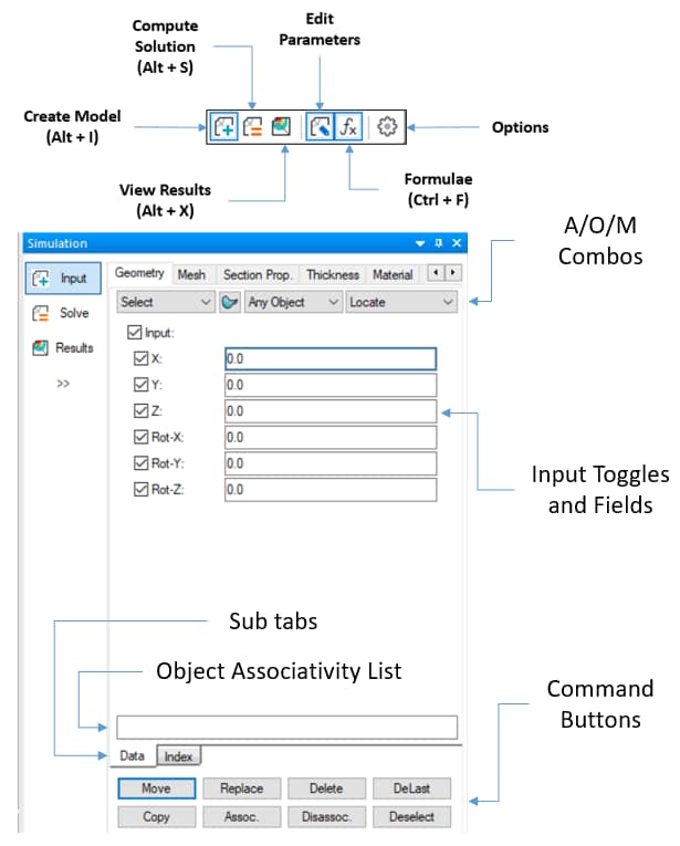
Most text-based user interaction will occur in one of the dialogs. There are three primary dialogs under the Simulation pane (Figure 2): one for model input (Input), one for solve execution options (Solve), and one for results post-processing (Results). Icons for these options are also available in the Main Toolbar:
- Create Model
,
- Compute Solution
,
- View Results
, along with
- Edit Parameters
,
- Formulae
, and
- Options
.
The Input and Results dialogs in the Simulation pane are divided into three sections (Figure 2):
- At the top are the tabbed Input/Results classes (e.g. Geometry, Mesh, Plot, Min/Max) and the Class/Action/Object/Method (C/A/O/M) combo-boxes which relate to the active class tab.
- The Geometry class tab will also display a Surface/Curve
toggle between the Action and Object combo-boxes to enable access surface/solid (
) or boundary/curve (
) Objects and Methods.
- The Geometry class tab will also display a Surface/Curve
- In the center, there are the input toggles, fields, combo-boxes & options associated with the current A/O/M configuration. Note that most input fields may be constant, parametric or formulaic.
- Below the input toggles, fields, combo-boxes & options, there may be sub tabs (e.g. Data, Index, Define, Assign, Settings) that allow the user to select a category of input or store/recall a solution/results setting.
- At the bottom of each dialog, there is a set of buttons which are used to invoke various commands specific to the input class and current C/A/O/M configuration.
- Common commands include Accept, Replace, Delete, Purge and De-select.
Input Dialog

Within the Input dialog (Figure 3), users can create/edit/delete geometry objects, mesh objects, material assignments, boundary conditions and other model inputs. This dialog is where all pre-processing operations will be performed, and where all model objects and assignments may be reviewed/updated/deleted. Note: inputs may be constant, parametric or formulaic.
The full list of supported Input classes are as follows:
- Geometry class
- Mesh class
- Section Properties class
- Thickness class
- Material class
- Load class
- Constraint class
- Solution ID class
- P-Discretization class
- H-Discretization class
- Sets class
- Parts class
The Input dialog can be accessed by either selecting “Input” from the Edit pulldown menu, the “Input” option in the Simulation pane, or by selecting any Input class such as Geometry, Mesh, Thickness, etc. from the Class pulldown menu. Alternatively, the Input dialog may be activated by selecting the “Create Model” icon from the Main Toolbar: .
Learn more in the Model Inputs Overview.
Solve Dialog
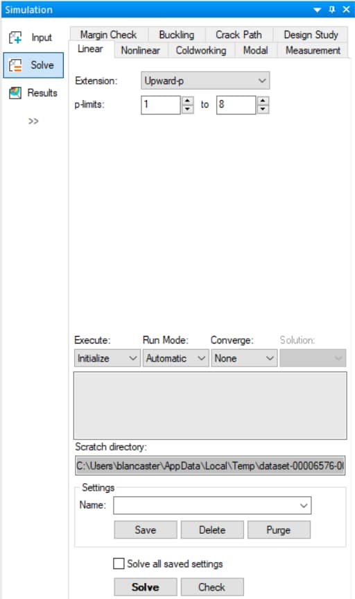
The Solve dialog (Figure 4) contains tabs for each solver type supported by StressCheck: Linear (default), Nonlinear, Modal, Buckling, Crack Path, Coldworking, Measurement, Margin Check and Design Study.
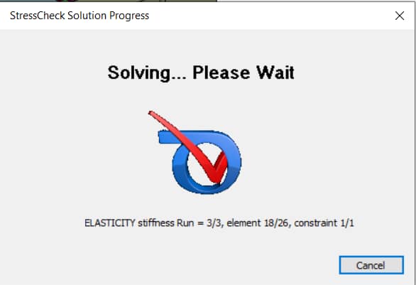
Once a specific solution type is selected, and the pertinent options for that solution type are chosen, you may specify the solver settings and execute the solution. Note that a toggle is available to solve all saved solution settings. To initiate the solution, click the Solve button; a solution progress dialog (Figure 5) will provide continuous updates on the solver steps until complete:
The full list of supported Solve execution options are as follows:
- Linear solver
- Nonlinear solver
- Coldworking solver
- Modal solver
- Buckling solver
- Margin Check solver
- Crack Path solver
- Design Study solver
The Solve dialog can be accessed by selecting “Solution” from the Edit pulldown menu, the “Solve” option in the Simulation pane, or by selecting the “Compute Solution” icon in the Main Toolbar: .
Learn more in the Solvers Overview.
Results Dialog
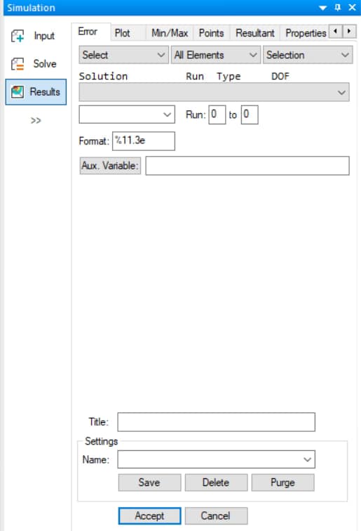
The Results dialog (Figure 6) contains several tabs, one for each type of post-processing option supported by StressCheck: error estimations (Error), solution plots (Plot), min/max extractions (Min/Max), points extractions (Points), resultant extractions (Resultant), geometric properties (Properties), fracture mechanics (Fracture) and settings for convergence criteria (Convergence Criteria).
StressCheck provides convenient means for extracting and displaying computed information:
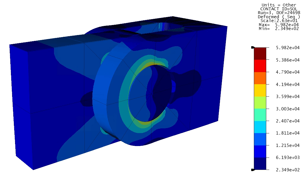
- In the case of post-processing via the Plot tab, a graphical display within the Model View (Figure 7a).
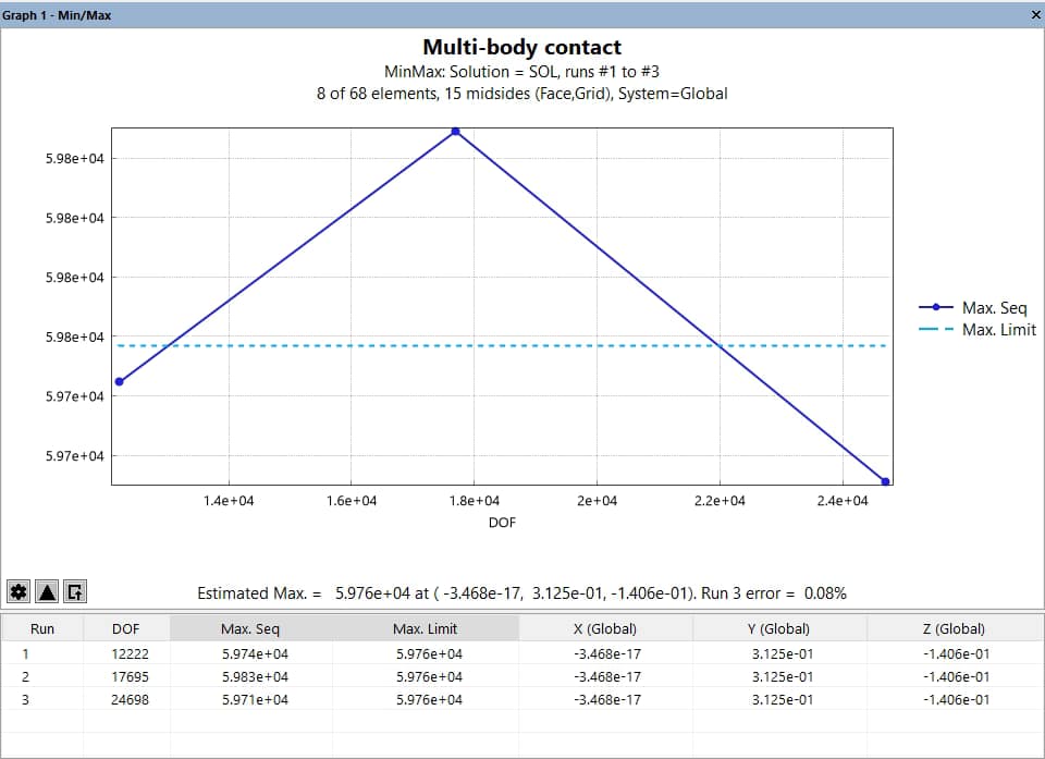
- When post-processing via all other tabs, a floating graph pane containing the requested output data in both plotted and tabular forms (Figure 7b).
The full list of supported Results classes are as follows:
- Error class
- Plot class
- Min/Max class
- Points class
- Resultant class
- Properties class
- Fracture class
- Convergence Criteria class
The Results dialog can be accessed by selecting “Results” from the Edit pulldown menu, the “Results” option in the Simulation pane, or by selecting the “View Results” icon in the Main Toolbar: .
Learn more in the Results Overview.
General Interface Conventions
Since StressCheck is based on Windows graphic user interface development tools, there are several standard conventions for interacting with the program. These and other important guidelines for navigating through the StressCheck interface are described in the following sections.
Keyboard Conventions
Tab Navigation
Use the Tab key to navigate between text fields. Tab alone navigates forward. Shift + Tab moves through the fields in reverse order.
Enter Key
Pressing the Enter key in the Input dialog or Results dialog is equivalent in functionality to clicking on the Accept button. Note that the Accept button should have focus in order for the Enter key to function in this regard.
Delete Key
Pressing the Delete key will perform the same object deletion operation as clicking the Delete button in the Input dialog.
Backspace Key
When an object being created requires more than two selections from the Model View display area such as polyline, spline curve, spline surface, or element, the Backspace key makes it possible to go back one step in order to select a different basis object.
Escape (Esc) Key
Pressing the Escape key will interrupt any time-consuming operation such as automeshing, model solution or animation. When necessary, the program will continue to perform the current task for a few seconds until it reaches a safe place to interrupt the computation. A warning message will then be displayed indicating the operation was interrupted, and the Error Log pane will display the following information (or similar):
WARNING
Process aborted.
Note: in some cases, a Cancel button will be available in the dialog (e.g., the Solution Progress dialog, the MeshSim Automesh Progress dialog) to perform the same function as the Escape Key.
Accelerator Keys
StressCheck makes several functions accessible by keyboard accelerators. Different dialogs have their own accelerators. Those that are defined when the Model View display area has focus are as follows:
- Ctrl + o : hide objects
- Ctrl + u : unhide all hidden objects
- Ctrl + i : invert selection
- Alt + o : open an existing StressCheck project file
- Alt + n : open a new StressCheck project file
- Ctrl + s : save the current contents of memory to the current StressCheck project file
- Ctrl + v : save the current contents of memory to a new StressCheck project file
- Ctrl + y : activate the redo procedure
- Ctrl + z : activate the undo procedure
- d : restore the default saved view
- v : save new default view
- Alt + i : activate the Input interface
- Alt + s : activate the Solve interface
- Alt + x : activate the Results interface
- c : center the model in the window
- r : switch to dynamic rotation
- t : switch to dynamic translation
- z : switch to dynamic zoom
- b : switch to dynamic box zoom
- a : show previous view
And those that are defined when a dialog or pane has focus are as follows:
- Ctrl c : copy contents of current text input field
- Ctrl x : cut contents of current text input field
- Ctrl v : cut contents of current text input field
- Shift delete : cut contents of current text field
- Shift insert : paste contents to current text field
- Alt backspace : undo/redo within a text input field
Mouse Conventions
Left Mouse Click
Clicking the left mouse button over the Model View display area will invoke the operation indicated by the current A/O/M settings.
Clicking the left mouse button on a vertex, edge or face of the Navigation Cube will result in re-orienting the global triad (and model display) to a standard view.
Right Mouse Click
Clicking the right mouse button over the Model View display area will abort any construction operation. It may also be used to refresh the display to reset highlighted objects, remove extraction markers, and clear plotted results.
Holding down the right mouse button for a short length of time (then releasing) will display a context menu. Learn more about context menu options in the Context Menu Overview.
Marquee Pick
When you position the mouse at the location where you wish to pick an object, then press and release the left mouse button, you perform a standard pick. However, if you press and hold the left mouse button, then drag the mouse, a marquee selection rectangle appears. When you release the mouse button, all objects of the currently selected type which lie within the marquee rectangle will be selected. As with standard selection, you must press the Shift key in order to add additional objects to the set of objects already selected. Similarly, you must press the Ctrl key while performing the selection in order to cancel previously selected objects.
Dynamic Mouse Operations
All dynamic display operations can be performed by dragging the mouse across the display area with the right mouse button depressed. This technique is used for rotation, translation, dynamic zoom and box zoom. The right mouse button is also used to select a point or node as the center of rotation.
For details on other keyboard/mouse functions, refer to Dynamic Display Operations Overview and Object Selection/Deselection Overview.
Input Conventions
Input Evaluation
StressCheck provides a mechanism for evaluating simple expressions and depositing the result in the input field. If you enter an equal sign (=) followed by an expression (FORTRAN or Mathematica conventions), the result will appear after pressing the Tab key.
For example, typing the following in an input field:
=sin(rad(45))^2
would convert 45 degrees to radians, evaluate the sine, and then square the result. It is also an option to utilize the FORTRAN convention for the exponentiation as in the following example:
=sin(pi/4)**2
All computations are performed in double precision whether or not the user supplies a decimal point. Input is not case sensitive. The expression may reference user-defined parameters, (e.g. pi, lo) and the StressCheck intrinsic functions.
Toggles
One of the most important input conventions is related to the use of a toggle button where there is an associated text input area.
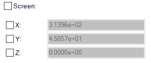
- When you see a toggle button turned on, the associated input field will be white, to indicate that manual keystroke input is enabled.
- When a toggle is turned off, the associated input field will be shaded and will be insensitive to keystroke input. In most situations, a disabled toggle button will indicate that the program is automatically assigning a value to the input parameter represented by the corresponding input field (Figure 8). This convention is followed throughout the program.
Parameter/Formula Popup Lists, Autofill & Validation
StressCheck supports the pop-up display of a list of currently defined parameters or formulas from any input field in the user interface where a parametric expression or formula name might be referenced. To obtain these lists, simply hold the Alt+P keys or Alt+F keys to obtain a list of parameters or formulas respectively, when the input definition field has focus. In Figure 9, Alt+P was used to display an autofill list of parameter names (with formula names listed in purple bold color):
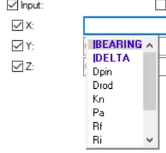
Once this autofill list is displayed, the user may press the up/down arrow keys to position the cursor over the desired parameter/formula name and press Enter, or simply left click on the parameter/formula name, to have that name appended to the current input field. To cancel the autofill list generation, simply click the Esc key or Ctrl+P.
StressCheck also supports the autofill list generation of candidate parameter/formula names based on the alphanumeric character(s) entered by the user, as well as the validation of the characters/strings present in the input field. Note: the input field will remain a red color as long as StressCheck detects the entry to be invalid. If one or more candidate parameter/formula names are filtered based on the character(s) entered thus far, these names will be listed directly below the last character entry:
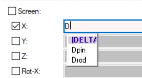
The user may then select the desired parameter/formula name from the filtered list and it will be added to the input field after the cursor location. Alternatively, the user may continue to type additional characters to continue to filter the autofill list options until the desired parameter remains, and then click it to add it to the input field. Note: if a candidate parameter or formula name cannot be identified based on the input character(s), the text (and input field) will turn a red color to indicate an invalid entry.
For more details on parameters and formulae, refer to Parameters & Rules Overview and Formula Overview, respectively.
 Serving the Numerical Simulation community since 1989
