Tip: Start typing in the input box for immediate search results.Can't find what you're looking for? Submit a support request here.
Linear Elastic Materials
Introduction
Linear elastic material properties describe models in which only elastic deformation is expected to occur (i.e. the maximum stress does not exceed the yield limit of the material), and the relationship between the stress and strain at any location remains linear (as described by Hooke’s Law). For models in which yielding and/or plastic deformation is expected to occur, an elastic-plastic material definition is required. For more info on elastic-plastic material definitions, refer to Elastic-Plastic Materials.
Linear Elastic Material Types
To define linear elastic material properties open the Model Inputs window and set the C/A/O/M to Material > Define > Linear > Selection and select the linear elastic material type from the “Type:” dropdown menu (Figure 1). The available linear elastic material definition types are:
- Isotropic
- Orthotropic
- Transversely Isotropic (Trans. Iso)
- Anisotropic
- Laminated Isotropic (Lamin. Iso.)
- Laminated Orthotropic (Lamin. Ortho)

Once a linear material type is selected you may then specify the defining material coefficients. The values of these coefficients may be constant, parametric, or formula input. Each linear material type is uniquely defined by a set of material coefficients which represent the different material properties (e.g. Elastic Modulus). The coefficients required for each material type are described in the following sections.
Isotropic

Isotropic materials have properties that are identical in all directions. Due to this symmetry, an isotropic material’s stiffness matrix is uniquely defined by the following two (2) engineering constants:
- E (Elastic/Young’s Modulus)
- v (Poisson’s Ratio)
Additionally, the following properties can be defined for use in modal analysis or thermal loading:
- Dens (Mass Density)
- a(th) (Coeff. of Thermal Expansion)
All material properties may be constant, parametric, or formula inputs.
Orthotropic

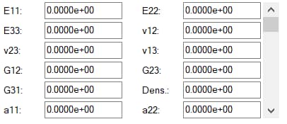
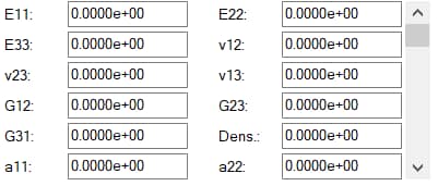
Orthotropic materials have properties defined along three mutually orthogonal axes/planes. As such, an orthotropic material’s stiffness matrix is uniquely defined by the following nine (9) engineering constants:
- E11, E22, E33 (Elastic/Young’s Modulus along each axis)
- v12, v23, v13 (Poisson’s Ratio in each plane)
- G12, G23, G31 (Shear Modulus in each plane)
Additionally, the following properties can be defined for use in modal analysis or thermal loading:
- Dens (Mass Density)
- a11, a22, a33 (Coefficients of Thermal Expansion along each axis)
All material properties may be constant, parametric, or formula inputs. Note: for plane-strain analysis G23 and G31 are not required, and for plane stress analysis E33, v23, v13, G23, and G31 are not required. Mass density and thermal expansion coefficients are only needed for modal analysis and thermal loading, respectively.
Specifying Principal Directions
For orthotropic materials, a coordinate system other than the global can be specified; a local coordinate system may be selected during the assignment of the material to the model. If the selected coordinate system is Cartesian (x, y, z), the material 1-axis is aligned with the x-axis of the selected coordinate system, the material 2-axis is aligned with the y-axis and the material 3-axis is aligned with the z-axis. If the selected coordinate system is cylindrical (r, θ, z), then the material 1- axis is aligned with the θ-direction, the material 2-axis is aligned with the r-direction and the material 3-axis is aligned with the z-axis.
Transversely Isotropic (Trans. Iso.)

Transversely Isotropic materials can be considered a special case of an orthotropic material in which material properties are symmetric about an axis that is normal to a plane of isotropy. In other words, material properties are identical along 2 of the 3 mutually orthogonal axes. In a transversely isotropic material, material properties are defined in terms of the 1-axis (flow direction) and the 2-axis (transverse direction). Due to the lack of a 3-axis, a transversely isotropic material’s stiffness matrix is uniquely defined by the following five (5) engineering constants:
- E11, E22 (Elastic/Young’s Modulus in the flow and transverse directions)
- v12, v23 (Poisson’s Ratio in the flow/transverse and transverse/transverse planes)
- G12 (Shear Modulus in the flow/transverse plane)
Note: here v23 is the Poisson’s ratio for a transverse contraction due to transverse extension. Additionally, the following properties can be defined for use in modal analysis or thermal loading:
- Dens (Mass Density)
- a11, a22 (Coefficients of Thermal Expansion)
All material properties may be constant, parametric, or formula inputs.
Specifying Flow and Transverse Directions
For Transversely Isotropic materials, a coordinate system other than the global can be specified; a local coordinate system may be selected during the assignment of the material to the model.
- If the selected coordinate system is Cartesian (x, y, z), the material 1-axis is aligned with the x-axis of the selected coordinate system, the material 2-axis is aligned with both the y-axis and the z-axis.
- If the selected coordinate system is cylindrical (r, θ, z), then the material 1- axis is aligned with the circumferential θ-direction, the material 2-axis is aligned with the r-direction and the z-axis.
Anisotropic

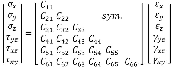
Anisotropic materials are materials whose properties vary in all directions and which lack the symmetry to be classified as Orthotropic or Transversely Isotropic. Their mechanical behavior can be described by the most general matrix form of Hooke’s Law in 3D with twenty-one (21) independent components of the stiffness matrix, [C], shown below:

When defining an anisotropic material in StressCheck the user must define each component of the material’s stiffness matrix. StressCheck accepts these components in the form of coefficients A1 through A21. The correspondence from Cij to Ai is shown below:

In addition to the 21 components of the stiffness matrix, the mass density (“Dens.”) may also be defined for use in modal analysis. Note: StressCheck does not support thermal loading for anisotropic materials. Hence, there is no input field for coefficients of thermal expansion.
Anisotropic: Planar Case
In the case of planar analysis (plane stress or plane strain) of an anisotropic material the z-components of Hooke’s law are eliminated and the equation reduces to the following:

StressCheck then accepts A1 through A6 as material coefficients. The correspondence from Cij to Ai becomes:

Note: In planar analysis the correspondence from Cij to Ai differs from that of 3D analysis.
Laminated-Isotropic (Lamin. Iso.) and Laminated-Orthotropic (Lamin. Ortho.)
This section is concerned with the definition of materials which are to be used in the construction of a laminated material. In StressCheck, laminated materials consist of multiple lamina through the thickness of a model. The Laminated-Isotropic and Laminated-Orthotropic material definitions are used to define the properties of each individual lamina within a laminated material. For more information on the ply-by-ply construction of laminated materials, please view Automatic Laminate Builder.
The material coefficients required for Laminated-Isotropic and Laminated-Orthotropic materials are the same coefficients as their non-laminated counterparts (i.e. Isotropic and Orthotropic, respectively) with the addition of a ply thickness parameter (Thick). For clarification on isotropic and orthotropic material definitions, please refer to the earlier sections of this article. The thickness parameter is utilized by StressCheck when generating an equivalent orthotropic stiffness matrix for the laminate (“Three-Dimensional Effective Elastic Constants for Thick Laminates” by Sun, C.T. and Li, S., Journal of Composite Materials, Vol. 22, pp. 629-639, 1988).

Laminated-Isotropic (Lamin. Iso.) materials are defined by the following material coefficients:
- E (Elastic/Young’s Modulus)
- v (Poisson’s Ratio)
- Dens (Mass Density)
- a(th) (Coeff. of Thermal Expansion)
- Thick (Ply Thickness)

Laminated-Orthotropic (Lamin. Ortho.) materials are defined by the following material coefficients:
- E11, E22, E33 (Elastic/Young’s Modulus along each axis)
- v12, v23, v13 (Poisson’s Ratio in each plane)
- G12, G23, G31 (Shear Modulus in each plane)
- Dens (Mass Density)
- a11, a22, a33 (Coefficients of Thermal Expansion along each axis)
- Thick (Ply Thickness)
 Serving the Numerical Simulation community since 1989
