Tip: Start typing in the input box for immediate search results.Can't find what you're looking for? Submit a support request here.
Loads Overview
Assignment of Loads in StressCheck
To assign load boundary conditions to a StressCheck model, select the Load tab in the Input dialog, set the Object and Method combo-boxes of the C/A/O/M to the desired configuration, and specify a load ID in the ID: combo-box. Then, select the object or objects to be loaded and input the load data. Loads may be constant, parametric or formula-based, and may be assigned to geometric or mesh objects. Finally, click on Accept to add the load assignment record to the load ID.

To assign a load record to a different load case, simply specify a different load ID in the ID: combo-box before clicking Accept. The below animation shows a Force/Moment load of Fz=100 lbf and Mz = 1000 lbf-in being assigned to a surface:
Summary of Loading Methods
Many methods are available for assigning loads, including Traction (applied stress), Force/Moment, Bearing (sinusoidal traction distribution in hole bore), TLAP (Bearing or Traction) and more. The loading objects/methods available depend on the currently selected reference (Planar, 3D, etc.).
For more details on the loading methods, refer to 2D Load Methods and 3D Load Methods.
General Boundary Loading Methods
Traction
Traction loading means that a distributed load (in force per unit area) is applied to a boundary.
Bearing
Bearing loading means that a normal sinusoidal traction (representing the interaction of a neat fit pin or fastener with a plate) is applied to a circular/cylindrical boundary by specifying the force vector components or force magnitude/direction.
Force/Moment (3D Only)
Force/Moment loading means that the directional components of force and moment vectors defined on a local system are applied to a flat co-planar surface as a statically equivalent linear traction distribution.
Spring Displacement
Spring displacement means that a traction load is applied through a displacement (in units of length) imposed on a distributed spring. The only restriction is that the spring coefficients and the imposed spring displacements must be in the same reference frame (i.e. Norm./Tan. → Norm./Tan.).
General Volume Loading Methods
Body Force
Body force loading means that the body is loaded by some volumetric load (in force per unit volume), such as by gravity or inertia due to acceleration.
Thermal
Thermal loading means that a temperature distribution (in degrees) will be specified on elements. Temperature distributions obtained from a heat transfer analysis are also available in 3D.
Point and Fastener Loading Methods
Point Loads
Point load means that a location on the elastic body (Point Force), or the core of a fastener element (Force Load), is loaded by a concentrated force.
Interference (Planar Only)
Magnitude of the diametral interference (in units of length) that can be specified to a fastener element.
For more information on fastener loading methods, refer to Fastened Connection Analysis Overview.
Global-Local Loading Methods
TLAP-Traction (3D Only)
Total point loads (TLAPs) obtained from the solution of a global model can be associated to faces or to surfaces of a solid model which are not part of a hole. The total point force/moment (in force/force-length units) is converted into tractions distributed over each face such that they are statically equivalent to the corresponding point load/moment.
TLAP-Bearing (3D Only)
This functionality allows for the importation of total load at points (TLAPs) representing fastener loads obtained from the solution of a global model, and their assignment to a set of selected faces or the surface of a solid model associated with a hole or bore. The fastener load force/moment (in force/forcelength units) is converted into bearing tractions distributed over the surface of the hole.
For more details on TLAP methods, refer to Total Load at a Point (TLAP) Implementation.
Residual Stress Loading Methods
SRS System (3D Only)
A subsurface residual stress/strain load (SRS) refers to a thin layer of residual or initial stress/strain just below the outer surfaces of a part, for example, due to high speed machining or shot peening. The stress distribution must be self-equilibrated in order to be a called residual stress distribution. SRS System refers to the usage of a Cartesian coordinate system for defining the local orientation of the distribution.
SRS Curve (3D Only)
A subsurface residual stress/strain (SRS) load refers to a thin layer of residual or initial stress/strain just below the outer surfaces of a part. SRS Curve refers to the usage of a geometry curve for defining the changing local orientation of the SRS distribution.
For more details on SRS, refer to Subsurface Residual Stress (SRS) Overview.
BRS (3D Only)
A bulk residual stress (BRS) load refers to residual stresses defined throughout the volume of material. The residual stress data may be imported into StressCheck or computed with the StressCheck incremental plasticity solver.
For more details on BRS, refer to Bulk Residual Stress (BRS) Overview.
Selecting Objects for Assignment to a Load ID
You may load an object (such as an edge, boundary, face, surface or element) or a group of objects during load assignment. An object is selected from the Model View by pointing to it and clicking on the left mouse button.
- A group of objects can be marquee selected by left-clicking and dragging the cursor until the desired group is completely enclosed in a rectangular box.
- Holding the Shift key down while left-clicking will allow selection of multiple objects for assignment.
- If the group includes objects which were not to be selected then individual objects can be removed from the group by holding the Ctrl key down while clicking on them.
- If you wish to cancel the current selection of objects, simply right-click on the Model View.
Note: assigning to geometric objects, if associated with elements, will result in the associated elements inheriting the assignment. It is recommended to assign loads to geometry whenever applicable in case the mesh is updated.
Specifying a Set for Assignment to a Load ID
Alternatively, if a there is a set definition containing a list of objects for assignment, the name of this set may be specified in the Set: combo-box instead of selecting the objects from the Model View. Simply select the name of the set, and the objects in the set list will automatically be selected in the Model View.
Load Directions
You may select the Norm./Tan. reference frame or the XY (Planar) or XYZ (3D) reference frame, the default of which is the Global system. The positive normal is understood to be the outward normal. To select a different reference frame, select the desired system from the System: combo-box.
In 2D, the direction of the tangent is such that moving in that direction the positive normal is to the right. Depending on your choice for direction, either the Normal and Tangent or the X and Y components will be highlighted. You may select either or both. For example, if you wish to apply a load only in the tangential direction, then turn on the checkbox in front of Tangent and turn off the checkbox in front of Normal.
In 3D, if the reference frame is the Normal/Tangent then only Normal traction or spring displacement can be applied (infinite tangencies).
Load Data Types
The loading data may be a constant, a parameter or a formula. For the case of thermal loading in 3D it is also possible to specify the solution vector corresponding to a Heat Transfer analysis. Once you run the heat transfer problem, the corresponding temperature distribution can be specified as thermal loading for the elasticity analysis. The only thing you need to do is to enter the name of the solution and run number from the heat transfer analysis.
Entering constant data is straightforward. Simply click on the appropriate box and key in the constant value. Entering parametric data means that a constant load value will be computed from the parametric expression entered in the input field. Any expression (up to 15 characters long) using already defined parameters and constants can be used. Constant and parametric loading is constant within the domain of each element.
If loading is specified by a formula then the formula name is entered into the input area. If the formula is defined in a coordinate system other than the global system, then the name of the coordinate system must be selected. A formula load may be defined in terms of spatial variables X, Y, Z, or R,T,Z depending on the coordinate system, and is evaluated at each element Gauss point. When a name is entered into one of the input fields, the program first checks whether or not the name corresponds to any defined parameter. If it does, then uses the value of the parameter for that input field. If the name is not a parameter, then it checks if there is a formula with that name.
Adding an Assignment to a Load ID
Once an object or group of objects are selected, and a load ID is specified in the ID: box, to add the new load assignment record to the record listbox directly below the C/A/O/M combo-boxes simply click the Accept button. Note: if an existing load assignment record has already been selected from the record listbox, you first must choose Set: “New set” or re-select the action, object, or method. Then, you are able to create the new load assignment record as usual.
Replacing/Deleting an Assignment to a Load ID
If the user wishes to edit the data in an existing load assignment record, or delete an existing load assignment record, the user first selects the load assignment record from the record listbox directly under the C/A/O/M combo-boxes. Once it is selected, the Status column will read “Selected”, signifying the record can be replaced (updated) or deleted.
Replacing a Load Assignment Record
Once a load assignment record is selected, the user may update the data in the Load tab, and then click Replace to update the load assignment record. After clicking Replace, the Accept button will become active and the Replace and Delete buttons will become inactive.
Deleting a Load Assignment Record
Once a load assignment record is selected, the user may click Delete to delete the load assignment record. After clicking Delete, the Accept button will become active and the Replace and Delete buttons will become inactive.
Removing All Load Assignment Records
To remove all load assignment records, regardless of load ID, click the Purge button.
Querying/Deleting/Purging Load ID’s via Edit Load Cases

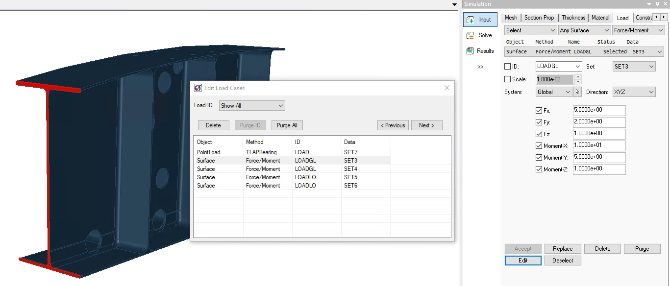
By clicking the Edit button at the bottom of the Load tab, a dialog is displayed to provide the user the ability to query single load records, delete single or multiple load records (Delete button), entire load ID’s (Purge ID button), or the full records list (Purge List). The Edit Load Cases dialog (Figure 2) allows the user to display all records (Show All) or sort loads by ID.
- Individual records shown in the list can be selected for query or deletion by clicking the corresponding row. The Load tab of the Input dialog will update to display the associated load record data, and the Model View will update to highlight the objects associated with the load record set name.
- Multiple records can be selected by holding Ctrl and picking each row desired for selection.
- A continuous series of records can be chosen by clicking on the first row, and then dragging the mouse to the last row, or hold down Shift while pressing the up or down arrow keys to extend the selection or directly click on the last row to complete the selection.
- The Previous and Next buttons can be used for cycling through individual records on the list. Once a record(s) has been selected, the Delete button can be used to remove it from the list.
- To remove an entire load ID, simply select the correct ID from the dropdown and click Purge ID.
- Purge All can be used at any time to remove all of the records from the list.
Checking a Load ID
StressCheck provides for checking the resultant of the applied mechanical loads for any load ID in the ID: combo-box, in any coordinate system and/or moment center.
Any Element/All Elements

To check the resultant of applied loads for a given load ID, select Check from the Action combo box and Any Element or All Elements from the Object combo box. If Any Element is selected, select the elements of interest from the Model View or select an element set from the Set: combo-box. Note: the Wetted Faces toggle may need to be disabled if internal elements are to be selected. Next, you may specify a coordinate system and moment center for the check. Finally, click on Accept and a load check summary of force and moment resultants will be returned in a tab above the Model View for either the selected elements (if Any Element) or the entire mesh (if All Elements, Figure 3).
Any Record

Alternatively, you may check the resultant of applied loads for individual load assignment records independent of load ID. Select Check from the Action combo box and Any Record from the Object combo box. This will automatically bring forth the Edit Load Cases dialog, allowing you to select one or multiple load records from the list. Once the load records of interest are highlighted, click on Accept, and StressCheck will compute the magnitude of the specified mechanical loads with respect to the system and moment center specified in the Load tab in a tab above the Model View (Figure 4). Note: the load record drop-down menu, ID and Set fields, and Replace and Delete buttons are all grayed out in the Input interface while the C/A/O/M is set to Check > Any Record > Selection.
To modify or add new load records, change the C/A/O/M to any other setting and all input fields will be re-activated.
Loaded Surface Querying
Surfaces can be queried for load assignments with the Surface Loads Browser. Querying a surface provides a list of loads applied to that surface (using an Any Surface assignment) and allows direct selection of the assigned loads for editing. This feature is useful if there are tens or hundreds of load assignments and you want to select a load applied to a particular surface without checking every single load assignment.
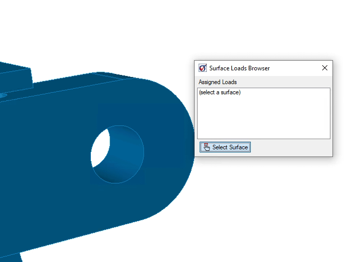
To use this feature, set the Object dropdown on the Load tab to “Any Surface”, then open the Surface Loads Browser from the Tools menu (Tools > Surface Loads…). Toggle surface query mode on with the selector icon shown in Figure 5:

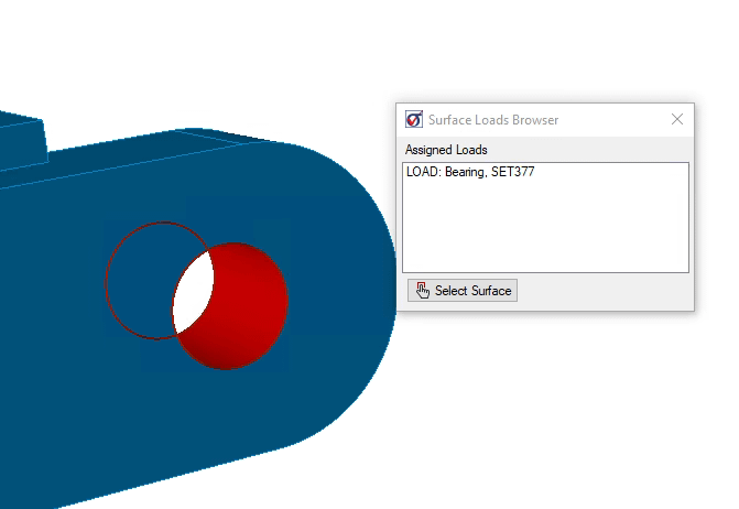
While surface query mode is on, select any surface. The surface query mode automatically turns off and all of the loads assigned to the selected surface are shown in the browser (Figure 6). If no loads are assigned, the browser provides feedback “no assigned loads”.

Selecting any load in the browser list updates the Load tab of the Input dialog with the selected load for editing. At any time the surface query mode can be toggled on and a new surface selected. If the Input dialog gains cursor focus, the Surface Loads Browser is automatically closed.
Loaded Surface Coloring
Load arrows for a given load case are displayed by selecting the load ID from the Display Load attributes drop down. To complement the load arrows, which are only drawn when elements with assigned loads are present, loaded surfaces change color when load display is toggled on. This is applicable to loads applied to Any Surface, with or without element association. Surfaces are only colored for the currently selected load case in the Display Load attributes drop down.
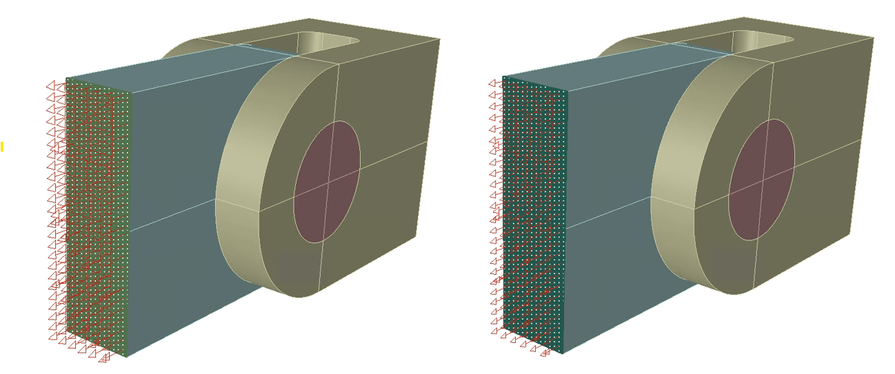
For example, open the Handbook file LugClevisFull.sci from the Parts Handbook. Turn off element display and turn on surface display. The loaded surface appears in green with white dots (Figure 7, left). If two or more loads are assigned to the same surface, it appears as a different color (Figure 7, right). This provides load assignment feedback regardless of whether a mesh is present. Toggle the load display off to remove the surface coloring feedback.

This feature is particularly useful when there are many load assignments, for example, to provide feedback that all fastener holes are loaded with a bearing load without manually checking every load assignment. For load cases where hundreds of surfaces require a load, for example a SRS load representing shot peening, this feature can be used to verify that all surfaces are loaded without duplicate loadings.
 Serving the Numerical Simulation community since 1989
