Tip: Start typing in the input box for immediate search results.Can't find what you're looking for? Submit a support request here.
Solvers Overview
Introduction
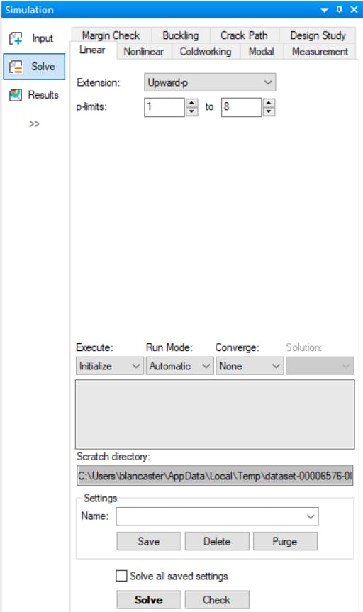
Once you have a properly defined model, including geometry, mesh, materials, loads, constraints, and solution ID definitions, you are ready to perform a StressCheck solution. The type of solver that you choose from the Solve dialog (accessed from the Simulation pane via Solve, Edit > Solution or by clicking the Compute Solution icon) depends on the goal of your analysis. To perform a linear analysis, for example, select the Linear tab (Figure 1):
In StressCheck, elements only represent the geometry and topology of the model. There is no need to change elements in order to perform one solution type or another. Analysis of specific attributes such as material properties and boundary conditions are easily provided so that the same topological model may be used to perform several different types of analysis. In fact, all attributes can be attached to a single model so that it is possible to define the model for any type of analysis, then simply choose the type of analysis to perform at any time.
In any case, StressCheck will construct a system of simultaneous equations and solve this system of equations to produce a set of solution vectors, one for each load case or mode shape for each element. The solution vectors are then used during post-processing to compute output quantities, such as stresses, strains, and displacements for problems of elasticity, or temperatures and gradients for heat transfer problems.
Since StressCheck post-processes “on the fly” from basic solution vector data, it is not necessary to plan ahead what data you will be interested in, or what locations in the model you will want to examine. This flexibility is one important advantage StressCheck has over other FEA programs, the ability to compute any engineering quantity, at any time, at any location in the model.
Now that you know that you do not have to worry about the data you will eventually want to examine after the solution, you can imagine that there is not much to do to prepare for a solution in StressCheck. All that is required is to choose the type of solution (via the Solve dialog tabs), select a few options, and activate the solution procedure. These options available in the Solve dialog shown in Figure 1.
The Solve dialog provides access to the various model solution procedures offered by StressCheck, including: Linear (Elasticity or Heat Transfer), Nonlinear (Elasticity or Heat Transfer), Modal, Buckling, Margin Check, Crack Path, Design Study, and Measurement Analysis. There are solution options specific to each type of analysis, and a few options which are required for any type of solution.
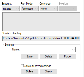
The solution specific options may be viewed by selecting the tab corresponding to a particular solution type and examining the lower half of the Solve dialog (as illustrated below in Figure 2 for the case of the Linear tab):
Each of these options will be discussed briefly in the sections which follow. In addition, the options associated with each type of solution will be described in greater detail in the Solver articles. NOTE: in previous releases, the options in Figure 2 were located within the Solve and Settings subtabs in the Solve dialog’s SOLVE! tab. The SOLVE! tab has been deprecated for an optimized solving experience.
Solution Options & Settings
When you are ready to activate a solution, whether it be a linear analysis, nonlinear analysis, or any other type of analysis, it is recommended to review the solution options available in the bottom half of the Solve dialog. The precise interpretation of each solution option sometimes depends on which type of analysis you are performing. For this reason, you should refer to the articles which discuss the specific analysis options in order to obtain precise instructions for using each option in the context of a particular analysis type.
To perform a particular type of analysis, first select the corresponding Solve dialog tab (e.g. Linear, Nonlinear, Modal), and then select the desired solution options. When ready to execute the solution, click the Solve button. The following sections provide a general explanation of the options found in the lower half of the Solve dialog.
Execute
The Execute option may be either “Initialize” or “Restart”.
- Choose “Initialize” when you wish to solve the problem for the first time, or you wish to remove previous solutions and re-solve the problem as though this were the first time. The meaning of “Initialize” depends somewhat on what type of analysis you are performing. If it is a linear analysis, Initialize if you wish to discard all previous solutions and to start over. If it is a nonlinear analysis, Initialize if you simply wish to compute a new nonlinear solution starting from an existing linear solution.
- Choose “Restart” if you have already solved the problem at least once and wish to proceed with the solution sequence or solution iteration where you left off. The meaning of “Restart” depends somewhat on what type of analysis you are performing. If it is a linear analysis, Restart if you wish to solve the next p-level in the sequence. If it is a nonlinear analysis, Restart if you wish to perform the next iteration of the nonlinear solution.
Run Mode
The Run Mode option may be either “Automatic” or “Stepwise”.
- An automatic solution will proceed without an opportunity for user intervention. For example, if you are running a linear solution, p = 1 to 4, the automatic solution will perform 4 solutions one right after the other.
- A stepwise solution will stop after each p-level is complete. After each step completes you are free to post-process, or even exit from the program. When you are ready to perform the next solution in the sequence, simply click the Solve action button.
Method
StressCheck uses a Direct solver for the solution of linear system of equations.
Converge
By default, two Converge options are available:
- “None” means that the number of runs is controlled by the settings in the Linear tab.
- “Error = 2%” means that the number of runs will be controlled by the global error of the solution. When the estimated relative error in energy norm is less than or equal to 2% (5% for 3D problems), the execution will stop. The highest polynomial order cannot go beyond the limits entered in the Linear tab.
Additional convergence criteria can be defined in the Settings tab of the Results interface as described in Convergence Criteria article.
Solution
The Solution option is enabled when there is an active Solution Configuration defined. Then, the user may select “All”, which will run all active Solution Configurations, or a specific Solution Configuration. To learn more about Solution Configurations, refer to Solution ID Overview.
Status Window
During the solution, the current status of the solution process is reported in the Status Window of the Solve dialog:
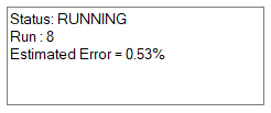
The Status Window indicates which run is currently in progress, and (potentially) additional information regarding estimated relative error in the energy norm (EREEN), maximum contact pressure error, current nonlinear iteration, unconverged elements, etc. The type of information shown depends on the type of analysis that is being performed (e.g. linear static, multi-body contact, nonlinear).
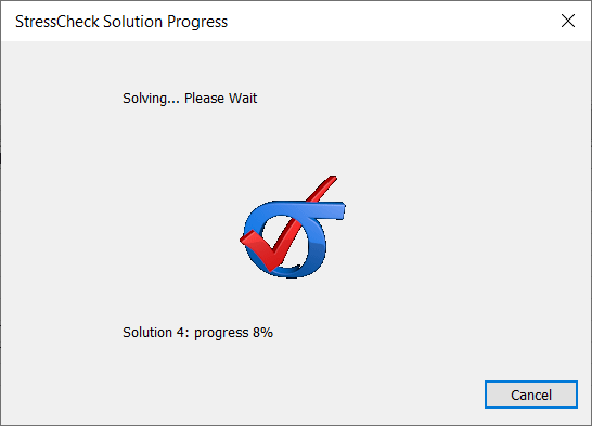
In addition, during the solution a “StressCheck Solution Progress” dialog will appear to indicate the solution progress:
Scratch Directory
The Scratch Directory can be changed in the File > Options dialog. Use the “Browse” button by “Path to Scratch Directory” to identify a directory path where you wish to have intermediate work files created. These files are disposable files, which can be quite large, generated during the solution procedure. These files may be directed to a scratch device where there is sufficient space on a temporary basis. If you prefer to simply type the path manually, you may enter it directly in the text field provided.
For users with multiple local hard drives it is recommended to move the scratch directory to the fastest hard drive for optimal solver performance. Do not put the scratch directory on a network drive, as this can lead to significant performance effects.
Settings Pane
The Settings pane provides an interface that will enable the user to record the current Solve dialog control settings for later use. The solution settings are stored in the database in alphabetical order, and are therefore also processed in alphabetical order when solving. It is important to name these records in such a way that the solutions will be performed in the desired order.
- When saving a new settings record, the user should supply a unique name in the combo box provided (e.g. “LinearSol”) to identify each record of settings. Use the Save button in the Settings pane to save the current settings in a record to be identified by the name provided. If the name provided matches an existing record, the existing record will be replaced.
- To retrieve a previously stored settings record, simply select the desired name from the combo box. The user interface will automatically be updated to reflect the settings stored in the chosen record. Then, click on the Solve button to solve that solution setting.
- Use the Delete button to remove the record identified by the name in the combo box.
- Use the Purge button to remove all settings records from the database.
- If the Handbook icon is enabled, the settings record will be solved when the “Solve All Saved Settings” option is enabled.
- If the Handbook icon is disabled, the settings record will be skipped when the “Solve All Saved Settings” option is enabled.
Solve Button
The “Solve” action button will activate the currently specified solution. If you wish to interrupt the solution after it has started, simply press the “Escape” key or click the “Cancel” button in the StressCheck Solution Progress dialog. The solution computation will continue until the program reaches a convenient place to stop. You may later restart the solution computation with the run that was interrupted.
Note: any solutions which were solved before the current solution was interrupted will be available for post-processing in the Results dialog.
Check Button
The “Check” action button will produce a report (dataset.chk) summarizing Parameters, Element Distortion, Geometric Properties, Material Properties, Applied Load, and the Disk Space required to perform the currently specified solution.
Solve All Saved Settings Option
This option will solve all saved solution settings stored in the Settings dropdown of the Settings pane. Note: this option is available from within the Linear tab only.
Export a Solution Settings File
To export a list of saved solution settings for later use, use File > Export and select the “StressCheck Settings file (*.scsettings)” filter. Then, provide a name representing the list of solution settings. Note: all results extraction settings in the current StressCheck project will also be exported to the .scsettings file.
Import a Solution Settings File
A StressCheck settings file may be imported to another StressCheck project by using File > Import and selecting the .scsettings file. The list of solution settings should be available in the Settings dropdown. Note: any results extraction settings stored in the imported .scsettings file will also be available in the Results dialog’s Settings dropdown.
Solvers
Below are the solver types supported in StressCheck, and accessible via the Solve dialog tabs.
Linear
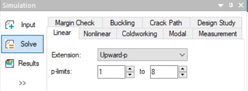
With the Linear solver, StressCheck supports Upward-p, Downward-p and Adaptive-p extensions. P-extensions may range between p=1 to p=8.
Linear analyses are the simplest type of solutions that can be performed in StressCheck. Moreover, a linear analysis is considered the first step in the hierarchy of analyses; for example, the same model used to perform a linear analysis may be used as the starting point for a nonlinear analysis.
To learn more about linear analyses in StressCheck, visit the Linear Analysis Overview.
Nonlinear
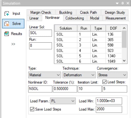
StressCheck supports Material (i.e. deformation and incremental theories of plasticity), Geometric (deformed shape incorporated in equilibrium equations) and General (Material + Geometric) nonlinearities.
Each nonlinear analysis starts from a previously computed linear solution; as a result, it is always important to verify the quality of the linear solution before attempting a nonlinear analysis.
To learn more about how nonlinear analyses are implemented in StressCheck, visit the Nonlinear Analysis Overview.
Coldworking (Planar Only)
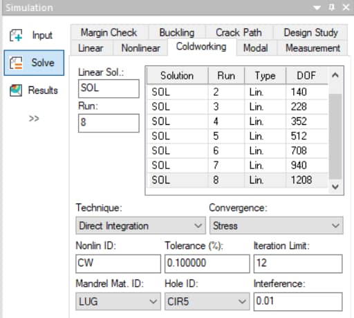
StressCheck provides a unique capability for simulating the effects of coldworking. This capability is based on the deformation theory of plasticity and requires the specification of a Hole ID (circle object).
The coldworked body is represented by a plane stress or plane strain model (Planar reference only). Similar to other nonlinear analyses, coldworking analyses use an existing linear solution for its starting point.
To learn more about coldworking analyses in StressCheck, visit the Coldworking Analysis Overview.
Modal
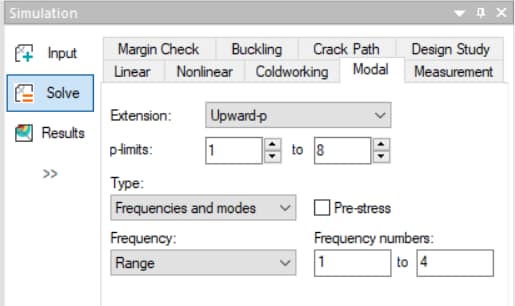
Modal analyses can be used to find natural frequencies and their corresponding mode shapes. Modal analyses can also take initial stresses into account, if desired.
To learn more about modal analyses in StressCheck, visit the Modal Analysis Overview.
Buckling (3D Only)
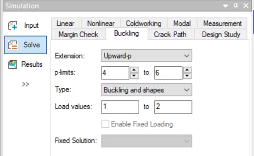
Buckling analyses in StressCheck are intended to be used to compute loading factors for models with specific loading conditions and their corresponding buckling shapes. This solution type is only available in the 3D reference.
To learn more about buckling analyses in StressCheck, visit the Buckling Analysis Overview.
Margin Check
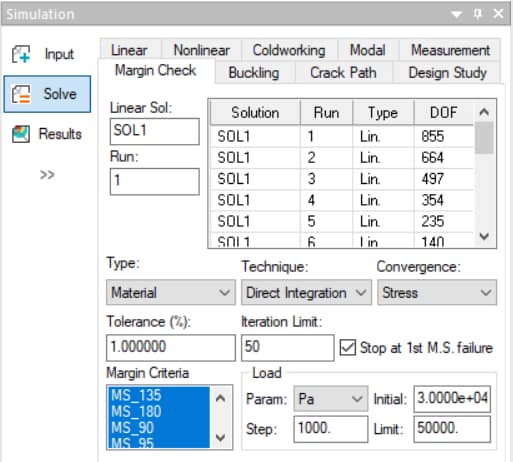
The Margin Check solver is a nonlinear analysis capability (material or general nonlinear) with failure criteria control (i.e. formula-based Margin Criteria). To solve a Margin Check problem a linear problem must be solved first. If a material nonlinear analysis is involved, a nonlinear material stress-strain law must be specified.
To learn more about margin check analyses in StressCheck, visit the Margin Check Analysis Overview.
Crack Path (Planar Only)
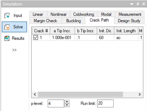
With the Crack Path solver, StressCheck computes the turning angles of one or more thru-cracks objects in a single sheet body. Crack Path analysis is limited to use in the Planar reference and requires that a set of model construction rules be carefully followed.
In contrast to other analysis modules in StressCheck, Crack Path analysis does not require that the user construct a finite element mesh in advance. Rather, the analysis procedure will automatically mesh the domain during the solution process.
To learn more about crack path analyses in StressCheck, visit the Crack Path Analysis Overview.
Measurement
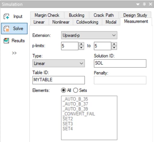
Measurement analyses are an advanced feature which are primarily used in research applications, in order to approximate either displacement components or temperature distributions with a given set of measured displacements or temperatures, respectively.
Design Study
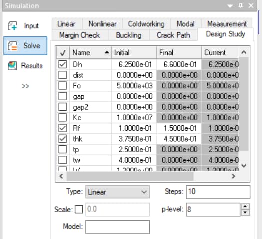
The Design Study solver makes it possible to evaluate design variations by selecting design variables which will be systematically changed during a series of solution computations.
To learn more about design study analyses in StressCheck, visit the Design Study Overview.
 Serving the Numerical Simulation community since 1989

