Tip: Start typing in the input box for immediate search results.Can't find what you're looking for? Submit a support request here.
Standard Engineering Functions
Introduction
StressCheck is based on the displacement formulation of the finite element method. Therefore the basic information generated by StressCheck is an approximation to the displacement vector components. This approximation is characterized by the set of standard shape functions and their coefficients. Thus, in the case of two-dimensional elasticity, the displacement vector components on the kth quadrilateral element are known in the form:

where n is the number of shape functions. The value of n depends on the polynomial degree p and whether the product or trunk space is used. Ni(ξ,η) (i=1,2,…,n) represent the standard shape functions defined in Introduction to Finite Element Analysis: Formulation, Verification and Validation by Barna Szabó and Ivo Babuška. All user-specified functions are computed from the displacement vector components. StressCheck computes a set of commonly used engineering functions, such as stresses, strains, etc. The available standard StressCheck functions, and corresponding symbols, are listed below for Planar, 3D and Axisymmetric references. In addition, any combination of the standard StressCheck functions can be computed through user-specified formulas or through the use of the StressCheck Calculator.
Planar/3D Elasticity Functions
Planar/3D Elasticity functions are described in terms of Cartesian (i.e. X, Y, Z) space.
Displacements
The following are symbols & standard functions for displacements in the Planar/3D reference:
| Ux | Displacement component in the x-direction ux |
| Uy | Displacement component in the y-direction uy |
| Uz | Displacement component in the z-direction uz |
| |U| | Total displacement |u| |
Strains
The following are symbols & standard functions for strains in the Planar/3D reference:
| Ex | Normal strain εx |
| Ey | Normal strain εy |
| Ez | Normal strain εz |
| Gxy | Shear strain γxy |
| Gyz | Shear strain γyz |
| Gxz | Shear strain γxz |
| E1 | 1st Principal strain ε1 |
| E2 | 2nd Principal strain ε2 |
| E3 | 3rd Principal strain ε3 |
| Eeq | von Mises strain εeq |
By definition the normal strains are:

And the shear strains are:

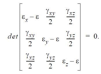
The principal strains are the eigenvalues of the strain tensor. They are the strain values ε which satisfy the condition:

In two-dimensional problems, γyz = γxz = 0. The three roots are the principal strains, denoted by ε1, ε2, ε3. In two-dimensional problems the principal strains are ordered such that ε1 ≥ ε2, and ε3 = εz. In three dimensions ε1 ≥ ε2 ≥ ε3. The normalized eigenvectors are the unit vectors which define the directions of the principal strains.
The equivalent strain is related to the von Mises theory of yield. For linear elastic isotropic materials:

And for elasto-plastic materials:

Stresses
The following are symbols & standard functions for stresses in the Planar/3D reference:
| Sx | Normal stress σx |
| Sy | Normal stress σy |
| Sz | Normal stress σz |
| Txy | Shear stress τxy |
| Tyz | Shear stress τyz |
| Txz | Shear stress τxz |
| S1 | 1st Principal stress σ1 |
| S2 | 2nd Principal stress σ2 |
| S3 | 3rd Principal stress σ3 |
| Seq | von Mises stress σeq |
| Tmax | Maximum shear stress τmax |
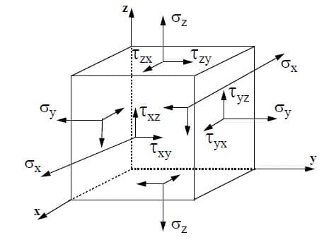
The sign convention for the stress tensor components is illustrated below. In two dimensions τxz = τzx = 0 and τyz = τzy = 0. The directional stresses, are computed multiplying the material stiffness matrix [E] by the strain tensor {ε}:


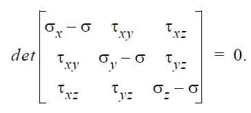
The principal stresses are the eigenvalues of the stress tensor. They are the stress values σ which satisfy the condition:

The three roots of the equation above are the principal stresses, denoted by σ1, σ2, σ3. In two-dimensional problems the principal stresses are ordered such that σ1 ≥ σ2 and σ3 = σz. In three dimensions σ1 ≥ σ2 ≥ σ3. The corresponding normalized eigenvectors are the unit vectors in the direction of the principal stresses.
The equivalent stress σeq is by definition:

σeq is related to the von Mises yield criterion. The maximum shear stress is, by definition:

where σ1 is the largest and σ3 is the smallest principal stresses. τmax is related to the Tresca yield criterion. In Planar Elasticity, the maximum shear stress is computed from σ1 and σ2.
Cylindrical System Extractions
If a local Cylindrical system is chosen for computation, the following conventions are used to relate the standard function symbols in Cartesian space (i.e. X, Y, Z) to their counterparts in Cylindrical space (i.e. R, T, Z):
X ⇒ R (radial)
Y ⇒ T (tangential/hoop)
Z ⇒ Z
For example, if a local Cylindrical system is selected for computation, and the standard function “Sx” is selected, the output will be the radial stress σr, and if the standard function “Sy” is selected, the output will be the tangential stress σt.
For an example of extracting results in cylindrical coordinates, refer to StressCheck Tutorial: Results in Cylindrical Coordinates (R, T, Z).
Axisymmetric (Axisym.) Elasticity Functions
Axisymmetric Elasticity functions are described in terms of (R, Z) space. It is assumed that there is no circumferential displacement (i.e. uθ = 0).
Displacements
The following are symbols & standard functions for displacements in the Axisymmetric reference:
| Ur | Displacement component in the R-direction ur |
| Uz | Displacement component in the Z-direction uz |
| |U| | Total displacement |u| |
Strains
The following are symbols & standard functions for strains in the Axisymmetric reference:
| Er | Normal strain εr in the radial direction |
| Ez | Normal strain εz in the Z-direction |
| Et | Normal strain εt in the circumferential direction |
| Grz | Shear strain γrz |
| E1 | Principal strain ε1 in the rz-plane |
| E2 | Principal strain ε2 in the rz-plane |
| Eeq | Equivalent strain εeq |
In Axisymmetric Elasticity, the displacement vector components ur(r, z) and uz(r, z) are computed for each element. The strains are then computed as:

The principal strains (ε1, ε2) are computed in the r-z plane as follows:

Note that the third principal strain (ε3) is equal to εt. The equivalent strain is:

Stress
The following are symbols & standard functions for stresses in the Axisymmetric reference:
| Sr | Normal stress σr |
| Sz | Normal stress σz |
| St | Normal stress σt |
| Trz | Shear stress τrz |
| S1 | Principal stress σ1 in the rz-plane |
| S2 | Principal stress σ2 in the rz-plane |
| Seq | Equivalent stress σeq |
| Tmax | Maximum shear stress τmax in the rz-plane |
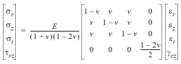
The stress components are determined from the stress-strain relationships. For isotropic materials for example, we have:

The principal stresses (σ1, σ2) are computed in the r-z plane as follows:

Note that the third principal stress (σ3) is equal to σt. The equivalent stress is:

And the maximum shear stress (τmax) is:

Special Functions
Additionally, special functions may available for some output classes (e.g. Plot, Min/Max, Points). These special functions include the error indicator, user-specified formula, the StressCheck Calculator, fracture mechanics parameters and multi-body contact solution functions. Note: fracture mechanics parameters require a radius of integration to be entered in the “Rad.” field.
| Error | Error Indicator. Available in the Plot output class only. |
| Fmla | Formula. Using this option, any mathematical expression containing the standard functions can be computed for a given solution. Available in the Plot, Min/Max and Points output classes. |
| Calc | Calculator. Using this option, any mathematical expression containing standard functions can be computed for any arbitrary combination of solutions. Available in the Plot, Min/Max and Points output classes. |
| K1 | Mode I stress intensity factor (SIF) via the Contour Integral Method (CIM). Available in the Points output class only. |
| K2 | Mode II stress intensity factor (SIF) via the Contour Integral Method (CIM). Available in the Points output class only. |
| K3 | Mode III stress intensity factor (SIF) via the Contour Integral Method (CIM). Available in the Points output class only when the reference is 3D. |
| T-str | T-stress. Available in the Points output class only. |
| J1p | Mode I energy release rate (ERR) via the path J-integral (J-path). Available in the Points output class only. |
| J2p | Mode II energy release rate (ERR) via the path J-integral (J-path). Available in the Points output class only. |
| J3p | Mode III energy release rate (ERR) via the path J-integral (J-path). Available in the Points output class only. |
| Initial Gap | Pre-solution (initial) gap measurement between contact pairs. Available in the Plot output class for the case of 3D multi-body contact solutions only. |
| Final Gap | Post-solution (final) gap measurement between contact pairs. Available in the Plot output class for the case of 3D multi-body contact solutions only. |
| Contact Press. | Contact pressures (surface tractions) developed between contact pairs. Available in the Plot output class for the case of 3D multi-body contact solutions only. |
For more information on the special functions:
 Serving the Numerical Simulation community since 1989
