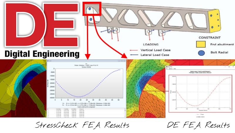
Extraction of minimum principal stresses for the aircraft keel section case study. Digital Engineering case study results (bottom right) compared well with StressCheck’s live dynamic extractions (bottom left, images courtesy of Digital Engineering/ESRD).
Introductory Remarks
In recent years, Digital Engineering began publishing articles on practical engineering simulation case studies, walk-thrus and software overviews for a variety of FEA software tools. In each article, FETraining developer and NAFEMS FEA training instructor Tony Abbey selected a commercially-available FEA software tool to analyze a mechanical component under various loads and constraints, and provided commentary, tips, tricks and process workflow of how he arrived at the results. His goal for each article was to focus on general instruction and best practices for FEA rather than in the particular FEA tool used for solving the problem.
With the consent of Mr. Abbey, ESRD selected four (4) case studies from his list of Digital Engineering simulation articles and were provided the geometric description, material properties and boundary conditions to solve these problems in StressCheck Professional.
For comparative and instructional purposes, ESRD then recorded and published video demonstrations of the modeling, solution and live dynamic results extractions of each case study to our Resource Library.
Note: while these were not “blind” case studies (the Digital Engineering case study results were known in advance), the video demonstrations show the unaltered, associated StressCheck process workflow, with solution verification provided for each result to ensure that the approximation error is sufficiently small.
Case Studies in Detailed Stress Analysis
Case Study #1: “Stress in Finite Element Analysis”, Digital Engineering May 2016
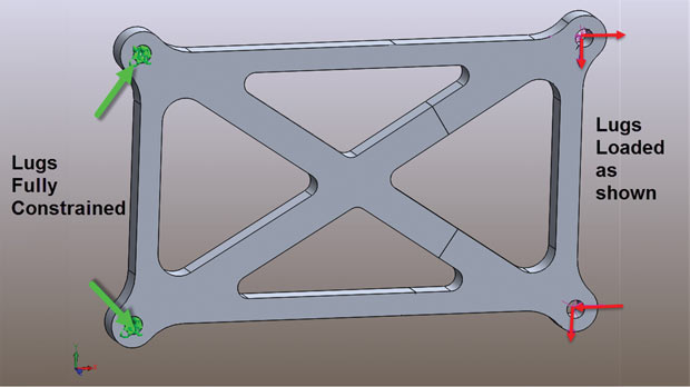
Cross brace structure showing constraint and loading set up (image courtesy of Digital Engineering).
In this particular case study, Mr. Abbey’s focus was to examine detailed cross-sectional stresses for a 3D solid cross brace geometry under off-axis loading. This involved defining multiple “zones” for extracting stresses, for a multitude of stress components and local system directions:
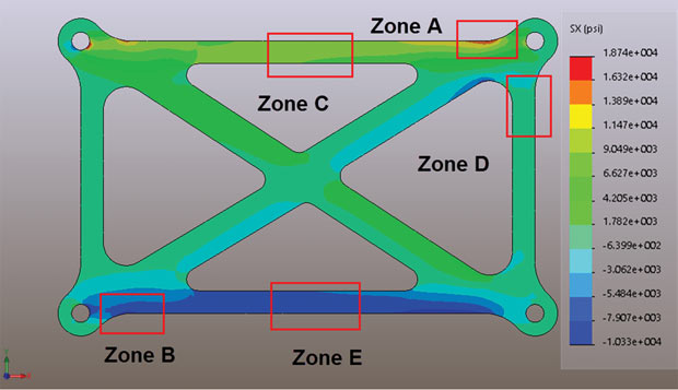
Zones of interest A through E and the SX stress distribution (image courtesy of Digital Engineering).
The following video demonstrates how StressCheck was used to reproduce the 3D detailed cross brace analysis and how cross-sectional lines were added after the solution for mesh-independent, curve-based stress gradient extractions. It is shown that StressCheck’s live, dynamic extractions compared favorably with Digital Engineering’s zone-based detailed stress results:
Case Study #2: “Dealing with Stress Concentrations and Singularities”, May 2017
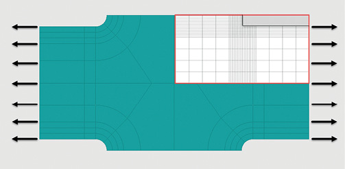
Geometry and mesh of filleted model (image courtesy of Digital Engineering).
For this case study, Mr. Abbey discussed the influence of stress singularities on the FEA solution, and why it is important to model radii and fillets in regions of interest for more accurate stresses if a subsequent fatigue analysis is the goal. He studied the convergence of the stresses in a shoulder fillet geometry by increasing the mesh refinement until the difference in his results was small:
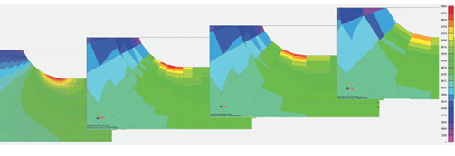
Stress distributions for the filleted model (image courtesy of Digital Engineering).
The following video demonstrates how the 3D shoulder fillet detailed stress analysis was performed in StressCheck, including the steps required to show convergence in the peak stresses. The results were nearly identical with Digital Engineering’s computed peak stress of 65.6 ksi:
Case Study #3: “Siemens FEMAP with NX NASTRAN Overview”, March 2018
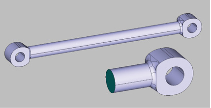
Initial imported geometry and cut-out region (image courtesy of Digital Engineering).
For this case study, Mr. Abbey utilized Siemens FEMAP with NX NASTRAN to model and solve a 3D solid tie rod under axial loading. He also recorded videos for how to perform the pre-processing, solution and post-processing and deployed them on his website, FETraining.net.
Below are the von Mises stress contours from the NX NASTRAN results, with an unaveraged peak von Mises stress of ~43.6 ksi:
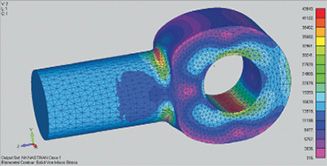
von Mises stresses (image courtesy of Digital Engineering).
The following video demonstrates how the full 3D tie rod geometry is imported into StressCheck, modified to remove all solid material outside of the cut-out region, automeshed with curved tetra elements, assigned the appropriate boundary conditions and solved with a p-extension process to increase degrees of freedom (DOF) on the fixed mesh.
Then, the converged peak von Mises stress was computed from the hierarchic sequence of linear solutions via a live dynamic extraction request and was observed to compare closely to Digital Engineering’s refined mesh NX NASTRAN result:
Case Study #4: “SOLIDWORKS Simulation Overview”, July 2018
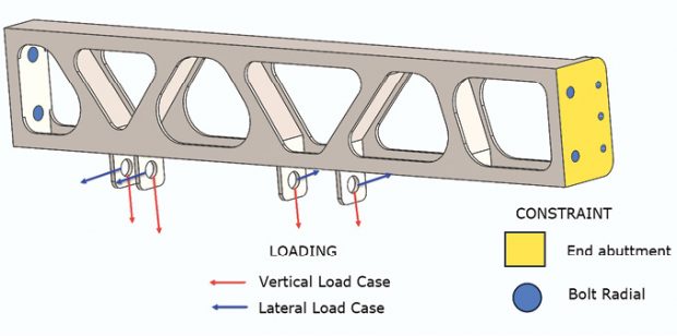
Applied loads and boundary conditions (image courtesy of Tony Abbey/Digital Engineering).
For this case study, Mr. Abbey utilized SOLIDWORKS from Dassault Systèmes to analyze a 3D solid aircraft keel section, in which several load cases (vertical and lateral loads) were applied to the structure’s attachment points via sinusoidal bearing distributions. From Mr. Abbey about the origin of this aircraft keel section structure:
The keel section is on the lower centerline of a combat aircraft fuselage. It transmits undercarriage loads into the fuselage. It also provides a load path through the lower fuselage section in overall bending and torsion loading due to maneuvers. The geometry has been created in SOLIDWORKS. Many of the smaller fillet radii have been defeatured in preparation.
Of interest were the peak von Mises stresses and minimum principal stresses in the left-hand end upper fillet radii (38.46 ksi and ~-37.5 ksi, respectively):
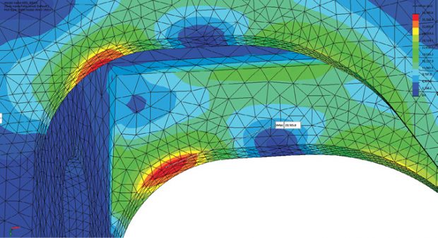
Von Mises stress distribution in the left-hand end upper fillet regions (image courtesy of Digital Engineering).
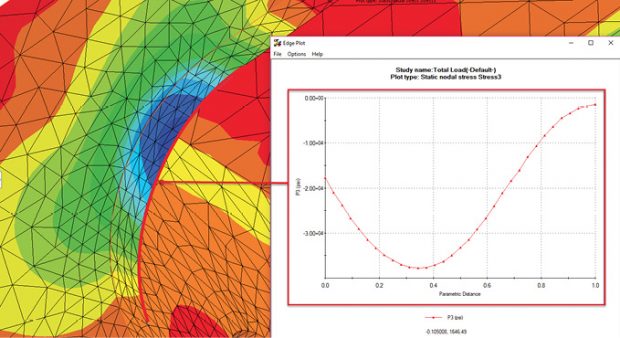
Minimum principal stress, P3, plotted around the left-hand end upper fillet (image courtesy of Digital Engineering).
The following video demonstrates how the 3D solid aircraft keel section was imported in StressCheck as a Parasolid and analyzed for detailed stresses in the left-hand end upper fillet regions for the vertical/lateral load cases and end abuttment/bolt radial constraints. The end abuttments were represented by symmetry constraints, and the bolt radial by stiff normal springs. The vertical and lateral load cases would be represented by sinusoidal bearing load distributions applied to the lug holes.
Again, the solution was obtained by increasing the polynomial order of the approximation functions on the fixed mesh, and the solutions for each load case were available for live dynamic processing.
It can be observed that the peak von Mises stress in the left-hand end upper fillet radii converges tightly to a value similar to that produced in Digital Engineering’s results, and the live dynamic principal stress gradient extractions were also quite similar in nature to those produced by Mr. Abbey in SOLIDWORKS probes:
Case Study Summary and a Note on Benchmarking
Many thanks to Mr. Abbey, FETraining.net and Digital Engineering for providing the model files to ESRD. The outcome of these case studies reinforce that only with careful engineering analysis methodologies, appropriate modeling assumptions, and tight control of approximation errors is meaningful to perform comparisons of stress results produced by different analysts using different FEA software tools.
Also, as we highlighted in the above case studies, the practice of solution verification is especially important for any benchmarking, round-robin or other comparisons involving the computation of the results of interest by numerical means for a well-defined mathematical problem. Reporting results without objective measures of the size of the approximation errors does not meet the technical requirements of Simulation Governance.
Finally, if you are interested in results of published benchmark problems solved with StressCheck, check out our solutions to the Standard NAFEMS Benchmarks:
 Serving the Numerical Simulation community since 1989





Leave a Reply
We appreciate your feedback!
You must be logged in to post a comment.