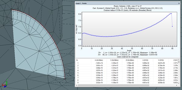
Once you solve a fracture mechanics problem using StressCheck’s Fracture Mechanics module, you won’t want to use another FEA tool for that purpose again. You will experience ease of use, realize superconvergence and receive high definition feedback information you need to guarantee the reliability and accuracy of the computed stress intensity factors (SIF) and energy release rates (ERR).
Fracture Mechanics Module

StressCheck has flexible, parametric crack modeling, automeshing and SIF extraction tools to easily assess one or multiple flaws in your CAD geometries. Embedded 3D flaws can be practically any shape, including circular, elliptical, and 3D splines. And SIF’s and ERR’s can be extracted from any location on the crack profile, independent of the mesh objects.
Key Features and Advantages
- Automatic meshing of embedded cracks in 2D and 3D.
- Cracks can be parametric (e.g. “a” and “c” parameters) and embedded in CAD with Parasolid operations.
- Cracks can be arbitrary shapes, even splines.
- Crack Edge (2D) and Crack Face (3D) assignments for easy automeshing.
- Boundary Layer mesher available in the MeshSim Advanced Module for optimal mesh grading around 3D cracks.
- Includes an automated Crack Path Analysis tool for 2D planar problems.
- One or more flaws can be introduced and their path analyzed under constant load conditions.
- Fully supports multi-body contact for capturing fastener propping, clamping, load transfer and other effects.
- Difference between propped and unpropped hole.
- Combined with the StressCheck COM API and da/dN databases, perform automated crack growth with COM-enabled tools like Excel, AFGROW, and MATLAB.
- Reliable computation of stress intensity factors (SIF) and energy release rates (ERR, via J-Integral).
- Point-and-click extractions of the SIF and ERR distributions with automatic convergence information.
- Provides essential feedback to support 2D or 3D crack growth analysis in tools such as AFGROW and NASGRO.
- Compute KI, KII, and T-Stress for cracks using the superconvergent contour integral method (CIM).
- Compute ERR’s JI, JII, and JIII for isotropic or orthotropic materials.
- KI, KII, and KIII can be obtained from the J-integral computation.
- Error estimation in all quantities can be determined automatically.
- No limit to the number of SIF’s or ERR’s extracted along a 3D crack.
- Can confidently extract within 5° of free edges and surfaces.
- Plot crack parameter changes (a/c) vs. SIF’s for one or more cracks.
- Table can be copied into Excel easily.
- Allows the computation of both the separated J-integral components JI, JII, JIII, and the corresponding stress intensity factors KI, KII, KIII for cracks in the presence of residual stresses.
- Contour Integral Method with a Loaded Crack (CIM-LC): Quickly compute mode I stress intensity factors with only the normal component of residual stress.
- J-Integral for Residual Stresses: If the full residual stress distribution is known, calculate JI, JII, and JIII.
- Convert J into K, providing KI, KII, and KIII in a residual stress field.
- Can compute SIF’s at cold worked regions.
Looking for Resources?
Recent News & Events
Quick Links
Testimonials
-
“As the United States Air Force continues to extend the service life of their aircraft the Aircraft Structural Integrity Program (ASIP) has had to refine the methods it uses to analyze and predict fatigue crack growth. Through the use StressCheck, coupled with AFGROW, we in A-10 ASIP have been able to more accurately model, predict and analyze critical aircraft structure for the A-10 and other types of structure for non-A-10 system managers. This also allows us within the A-10 to more accurately assess risk for decision makers, streamline aircraft inductions into scheduled maintenance and reduce cost for total life cycle management.”
A-10 ASIP Manager
 Serving the Numerical Simulation community since 1989


