By Dr. Barna Szabó
Engineering Software Research and Development, Inc.
St. Louis, Missouri USA
Generally speaking, philosophers are much better at asking questions than answering them. The question of distinguishing between science and pseudoscience, known as the demarcation problem, is one of their hotly debated issues. Some even argued that the demarcation problem is unsolvable [1]. That may well be true when the question is posed in its broadest generality. However, this question can and must be answered clearly and unequivocally in the engineering sciences.
That is because, in the engineering sciences, we rely on validated models of broad applicability, such as the theories of heat transfer and continuum mechanics, the Maxwell equations, and the Navier-Stokes equations. Therefore, we can be confident that we are building on a solid scientific foundation. A solid foundation does not guarantee a sound structure, however. We must ensure that the algorithms used to estimate the quantities of interest are also based on solid scientific principles. This entails checking that there are no errors in the formulation, implementation, or application of models.
In engineering sciences, we classify mathematical models as ‘proper’ or ‘improper’ rather than ‘scientific’ or ‘pseudoscientific’. A model is said to be proper if it is consistent with the relevant mathematical theorems that guarantee the existence and, when applicable, the uniqueness of the exact solution. Otherwise, the model is improper. At present, the large majority of models used in engineering practice are improper. Following are examples of frequently occurring types of error, with brief explanations.
Conceptual Errors
Conceptual errors, also known as “variational crimes”, occur when the input data and/or the numerical implementation is inconsistent with the formulation of the mathematical model. For example, considering the displacement formulation in two and three dimensions, point constraints are permitted only as rigid body constraints, when the body is in equilibrium. Point forces are permitted only in the domain of secondary interest [2], non-conforming elements and reduced integration are not permitted.
When conceptual errors are present, the numerical solution is not an approximation to the solution of the mathematical problem we have in mind, in which case it is not possible to estimate the errors of approximation. In other words, it is not possible to perform solution verification.
Model Form Errors
Model form errors are associated with the assumptions incorporated in mathematical models. Those assumptions impose limitations on the applicability of the model. Various approaches exist for estimating the effects of those limitations on the quantities of interest. The following examples illustrate two such approaches.
Example 1
Linear elasticity problems limit the stresses and strains to the elastic range, the displacement formulation imposes limitations on Poisson’s ratio, and pointwise stresses or strains are considered averages over a representative volume element. This is because the assumptions of continuum theory do not apply to real materials on the micro-scale.
Linear elasticity problems should be understood to be special cases of nonlinear problems that account for the effects of large displacements and large strains and one of many possible material laws. Having solved a linear problem, we can check whether and to what extent were the simplifying assumptions violated, and then we can decide if it is necessary to solve the appropriate nonlinear problem. This is the hierarchic view of models: Each model is understood to be a special case of a more comprehensive model [2].
Remark
Theoretically, one could make the model form error arbitrarily small by moving up the model hierarchy. In practice, however, increasing complexity in model form entails an increasing number of parameters that have to be determined experimentally. This introduces uncertainties, which increase the dispersion of the predicted values of the quantities of interest.
Example 2
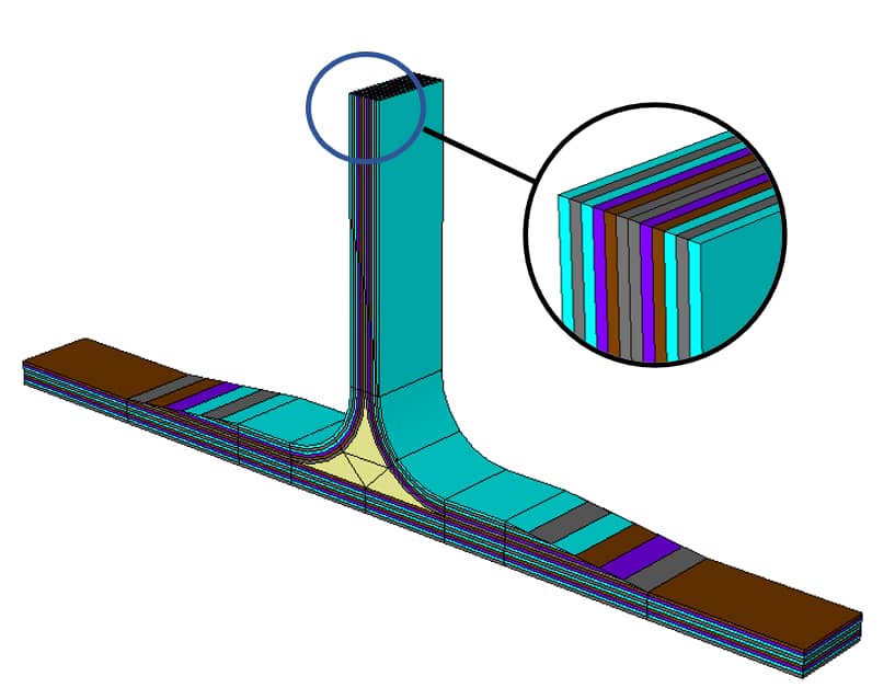
In many practical applications, the mathematical problem is simplified by dimensional reduction. Within the framework of linear elasticity, for instance, we have hierarchies of plate and shell models where the variation of displacements along the normal to the reference surface is restricted to polynomials or, in the case of laminated plates and shells, piecewise polynomials of low order [3]. In these models, boundary layer effects occur. The boundary layers are typically strong at free edges. These effects are caused by edge singularities that perturb the dimensionally reduced solution. The perturbation depends on the hierarchic order of the model. Typically, the goal of computation is strength analysis, that is, estimation of the values of predictors of failure initiation. It must be shown that the predictors are independent of the hierarchic order. This challenging problem is typically overlooked in finite element modeling. In the absence of an analytical tool capable of guaranteeing the accuracy of predictors of failure initiation, it is not possible to determine whether a design rule is satisfied or not.

Numerical Errors
Since the quantities of interest are computed numerically, it is necessary to verify that the numerical values are sufficiently close to their exact counterparts. The meaning of “sufficiently close” is context-dependent: For example, when formulating design rules, an interpretation of experimental information is involved. It has to be ensured that the numerical error in the quantities of interest is negligibly small in comparison with the size of the experimental errors. Otherwise, preventable uncertainties are introduced in the calibration process.
Realizing the Potential of Numerical Simulation
If we examine a representative sample of mathematical models used in the various branches of engineering, we find that the large majority of models suffer from one or more errors like those we described above. In other words, the large majority of models used in engineering practice are improper. There are many reasons for this, caused mainly by the obsolete notion of finite element modeling, deeply entrenched in the engineering community.
As noted in my earlier blog, entitled Obstacles to Progress, the art of finite element modeling evolved well before the theoretical foundations of finite element analysis were established. Engineering books, academic courses, and professional workshops emphasize the practical, intuitive aspects of finite element modeling and typically omit cautioning against variational crimes. Even some of the fundamental concepts and terminology needed for understanding the scientific foundations of numerical simulation are missing. For example, a senior engineer of a Fortune 100 company, with impeccable academic credentials earned more than three decades before, told me that, in his opinion, the exact solution is the outcome of a physical experiment. This statement revealed a lack of awareness of the meaning and relevance of the terms: verification, validation, and uncertainty quantification.
To realize the potential of numerical simulation, management will have to exercise simulation governance [4]. This will necessitate learning to distinguish between proper and improper modeling practices and establishing the technical requirements needed to ensure that both the model form and approximation errors in the quantities of interest are within acceptable bounds.
References
[1] Laudan L. The Demise of the Demarcation Problem. In: Cohen R.S., Laudan L. (eds) Physics, Philosophy and Psychoanalysis. Boston Studies in the Philosophy of Science, vol 76. Springer, Dordrecht, 1983.[2] Szabό, B. and Babuška, I. Finite Element Analysis. Method, Verification, and Validation (Section 4.1). John Wiley & Sons, Inc., 2021.[3] Actis, R., Szabó, B. and Schwab, C. Hierarchic models for laminated plates and shells. Computer Methods in Applied Mechanics and Engineering, 172(1-4), pp. 79-107, 1999.[4] Szabó, B. and Actis, R. Simulation governance: Technical requirements for mechanical design. Computer Methods in Applied Mechanics and Engineering, 249, pp.158-168, 2012.Related Blogs:
- Where Do You Get the Courage to Sign the Blueprint?
- A Memo from the 5th Century BC
- Obstacles to Progress
- Why Finite Element Modeling is Not Numerical Simulation?
- XAI Will Force Clear Thinking About the Nature of Mathematical Models
- The Story of the P-version in a Nutshell
- Why Worry About Singularities?
- Questions About Singularities
- A Low-Hanging Fruit: Smart Engineering Simulation Applications
 Serving the Numerical Simulation community since 1989


Leave a Reply
We appreciate your feedback!
You must be logged in to post a comment.