By Dr. Barna Szabó
Engineering Software Research and Development, Inc.
St. Louis, Missouri USA
Isogeometric Analysis (IGA) was introduced in a paper published in 2005 [1], where it was presented as an alternative to the standard, polynomial-based finite element analysis (FEA). By that time, finite element analysis had a solid scientific foundation and was firmly established as a branch of applied mathematics. Also, implementations based on the algorithms described in reference [2] were in professional use. Bearing this in mind is important to avoid confusion with earlier implementations of the finite element method found in legacy FEA software. Those implementations are based on the pre-scientific thinking of the 1960s and 70s. When evaluating IGA, it should be compared with the finite element method based on the science of finite element analysis, not the outdated implementations preserved in legacy FEA software.
Finite Element Fundamentals
We should understand the finite element method as a set of algorithms designed to approximate the exact solutions of partial differential equations cast in variational form. The approximating functions are mapped polynomials characterized by the finite element mesh Δ, the assigned polynomial degrees p, and the mapping functions Q [2]. The boldface symbols indicate arrays, signifying that each element may have a different polynomial degree and mapping function. These entities define the finite element space S(Δ,p,Q). The finite element solution uFE is that function in S(Δ,p,Q), which minimizes the error measured in a norm that depends on the formulation, usually the energy norm. Formally we have:
||u_{EX} - u_{FE}||_{E} = \min_{u \in S(\Delta,\mathbf{p},\mathbf{Q})}||u_{EX}-u||_{E}\qquad (1)where uEX is the exact solution and ∥.∥E is the energy norm [2]. The basis functions are continuous, but their derivatives normal to the element boundaries may be discontinuous. Of particular interest are hierarchic sequences of finite element spaces S1 ⊂ S2 ⊂ S3 … because the corresponding finite element solutions are guaranteed to converge to the exact solution, allowing estimation of the limit values of the quantities of interest. This makes solution verification possible, which is an essential technical requirement in numerical simulation.
Isogeometric Analysis
IGA is one possible implementation of the p-version of the finite element method. Its distinguishing features are: (a) it retains the CAD geometry, (b) the basis functions are the same as those used for CAD representation, typically B-splines or NURBS, and (c) it provides for the enforcement of the inter-element continuity of the derivatives of the basis functions.
At first glance, retaining the CAD model appears to be very advantageous. However, CAD models typically consist of multiple NURBS patches containing small gaps or overlaps. These patches may have been trimmed or joined in ways that disrupt the continuity required for IGA. Therefore, these models need to be edited, or “repaired”, before IGA can be applied. The necessity for editing to produce watertight CAD models also applies to mesh generators, computer numerical control (CNC) machining, and 3D printing.
In addition, the CAD models must be transformed into a format suitable for IGA. This transformation may involve reconstructing a CAD solid using IGA-compatible patches. In the context of IGA, the term “patch” refers to a continuous segment of the domain that is described by a single set of basis functions. Enforcement of the continuity of the basis functions across patch boundaries is a requirement.
IGA provides the option to enforce the continuity of one or more derivatives of the basis functions. In addition to the basis functions, the components of a patch include control points that define the geometric configuration and a knot vector that defines where the basis functions transition or change. The knot vector determines the degree of continuity of the basis functions at these transitions. – If this sounds complicated, that is because it is. Fortunately, a simpler way of handling the mapping problem associated with high-order finite element methods exists. This is discussed in the next section.
The term “k-refinement” is used to indicate that all derivatives up to and including the kth derivative of the basis functions are continuous. This is then put on par with the terms “h-refinement” and “p-refinement.” However, this is misleading for the following reason: In h- and p-refinements, the number of degrees of freedom (DOF) is increased either by decreasing the size of the largest element in the mesh (h) or by increasing the lowest polynomial degree of elements (p). In k-refinement, on the other hand, the DOF are decreased when higher continuity is enforced than the minimum required by the formulation. Therefore, “k-restriction” would be the correct term. Referring to equation (1), we see that imposing any restriction on the finite element space cannot possibly decrease the error of approximation in the norm of the formulation. Therefore, we can speak of h-convergence or p-convergence but not of k-convergence.
Mapping for High-Order Finite Element Methods
High-order finite element methods, when used in conjunction with properly defined meshes, have been shown to be effective in controlling the errors of approximation, provided that the primary sources of error are the size of the elements and the polynomial degrees assigned to the elements. Additional errors arise from using numerical integration, approximating the boundaries of the solution domain by mapped polynomials, and enforcing essential boundary conditions. It is necessary to ensure that these secondary errors are negligibly small in comparison to the primary errors.
A method for approximating curved surfaces with polynomials was developed in the early 1990s and implemented in ESRD’s StressCheck®. The approximation is based on using optimal (or nearly optimal) collocation points. Although the approximated surface is only continuous, and its derivatives may be discontinuous, the errors of approximation caused by such mappings have been shown to be negligibly small. The following example illustrates that even when all derivatives of the underlying exact solution are continuous, mapping elements using 5th-order polynomials and the Chen-Babuška collocation points [3] and enforcing only the minimal continuity required by the formulation yields very satisfactory results.
Example: Free Vibration of a Spherical Shell
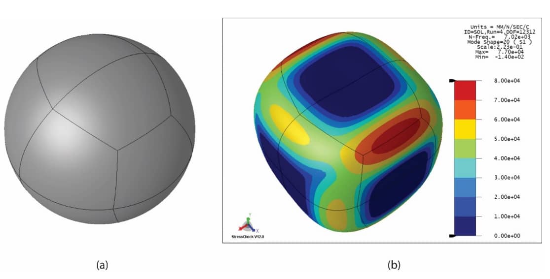
We consider the free vibration of a spherical shell. The shell, shown in Fig. 1(a), has a radius of 100 mm, wall thickness of 1.00 mm, modulus of elasticity of 1.80E5 N/mm2, Poisson’s ratio of 0.333, and mass density of 7.86E-9 Ns2/mm4 (7860 kg/m3). The goal of computation is to find the first twenty eigenvalues and show that the numerical error is less than 1%.
For the shell model, we chose the anisotropic product space (p,p,3), meaning that the displacement components are approximated by polynomials of degree p in the tangential directions to the mid-surface of the shell but fixed at degree 3 in the direction of the normal. The formulation requires that the displacement components be continuous across element boundaries.
The 20th eigenfunction and the contours of the corresponding first principal stress are shown in Fig. 1(b). The contours were not smoothed, yet there is no noticeable discontinuity in the stress at the inter-element boundaries.
Since the sphere is not constrained, the first six eigenvalues are zero. All eigenvalues converge strongly. For example, the 20th eigenvalue is 7021 Hz, which does not change as p increases from 6 to 8. Repeated eigenvalues occur; hence, the mode shapes are not uniquely defined.

Figure 1: (a) Spherical shell, automesh, 16 elements. (b) The 20th eigenfunction and the contours of the corresponding first principal stress (p=8, product space). The images were generated by StressCheck 12.0.
The IGA Challenge
Contrary to various claims, IGA is not a new paradigm in the numerical approximation of partial differential equations; it is simply an alternative implementation of the p-version of the finite element method. I will refer to the implementation of the p-version documented in reference [2] as the standard implementation. In this standard implementation, only the minimal required level of continuity (denoted as C0) is enforced to ensure applicability to the broadest class of problems admitted by the formulation.
Advocates of IGA have presented examples demonstrating that it requires fewer DOF to solve certain problems compared to the standard implementation of the p-version. However, the basis for comparison should be the operation count, not the DOF. This is because, while enforcing the continuity of derivatives decreases the number of DOF, it increases the density of the stiffness and mass matrices. A challenge must be based on a class of problems sufficiently large to be of interest from the perspective of engineering practice, justifying the investment associated with code development. It must be demonstrated that IGA performs better in obtaining quantities of interest and estimating their relative errors. As far as I know, no such claim has been formulated and substantiated.
References
[1] Hughes, T.J., Cottrell, J.A. and Bazilevs, Y. Isogeometric analysis: CAD, finite elements, NURBS, exact geometry and mesh refinement. Computer Methods in Applied Mechanics and Engineering, 194(39-41), pp. 4135-4195, 2005. [2] Szabό, B. and Babuška, I. Finite Element Analysis. Hoboken, NJ. John Wiley & Sons, Inc., 1991. The 2nd edition, Finite Element Analysis: Method, Verification and Validation, was published in 2021. [3] Chen, Q. and Babuška, I. Approximate optimal points for polynomial interpolation of real functions in an interval and in a triangle. Computer Methods in Applied Mechanics and Engineering, 128(3-4), pp. 405-417, 1995.Related Blogs:
- Where Do You Get the Courage to Sign the Blueprint?
- A Memo from the 5th Century BC
- Obstacles to Progress
- Why Finite Element Modeling is Not Numerical Simulation?
- XAI Will Force Clear Thinking About the Nature of Mathematical Models
- The Story of the P-version in a Nutshell
- Why Worry About Singularities?
- Questions About Singularities
- A Low-Hanging Fruit: Smart Engineering Simulation Applications
- The Demarcation Problem in the Engineering Sciences
- Model Development in the Engineering Sciences
- Certification by Analysis (CbA) – Are We There Yet?
- Not All Models Are Wrong
- Digital Twins
- Digital Transformation
- Simulation Governance
- Variational Crimes
- The Kuhn Cycle in the Engineering Sciences
- Finite Element Libraries: Mixing the “What” with the “How”
- A Critique of the World Wide Failure Exercise
- Meshless Methods
 Serving the Numerical Simulation community since 1989


Leave a Reply
We appreciate your feedback!
You must be logged in to post a comment.