SAINT LOUIS, MISSOURI – January 29, 2018
In ESRD’s last S.A.F.E.R. Simulation post, we profiled the challenges that structural engineers encounter when using legacy-generation finite element analysis (FEA) software to perform high-fidelity stress analysis of mixed metallic and composite aerostructures designed to be higher-performing and more damage tolerant over longer lifecycles. We went so far as to question whether because of these challenges the democratization of simulation was a realistic or safe goal if it means putting the current generation of expert FEA software tools into the hands of the occasional user or non-expert design engineer.
In this third of our multi-part series on “S.A.F.E.R. Numerical Simulation for Structural Analysis in the Aerospace Industry” we will examine why Numerical Simulation is not the same as Finite Element Modeling and what this means to the structural analysis function within the A&D industry. We’ll start by sharing a brief history of the finite element method.
Legacy Finite Element Modeling
The finite element method (FEM) used to solve problems in computational solid mechanics is now over 50 years old. Over the decades there have been many commercial improvements in analysis capabilities, user interfaces, pre/post processors, high-performance computing, pricing and licensing options. However, what has not changed is that nearly all of the large general-purpose FEA codes in use today for mechanical analysis are built upon the same underlying legacy FEM technology base.
How can someone identify a legacy FEA code? If it has more element types than you can count on one hand, if answers are dependent on the mesh, if different analysis types (e.g. linear, non-linear, thermal, modal) require different elements and models using different computational schemes, or if there is no explicit measurement of solution accuracy, then it is based on legacy FEM.
In these older implementations of the FEM the focus of the analyst shifts from the eloquence of the underlying method to the minutia of the model. These details include the selection of element types, location of nodes, and refinement of mesh among a long list of user-dependent judgement calls, assumptions, and decisions. It is no surprise for many users of legacy FEA codes that the task of creating the right mesh consumes most of the analyst’s time such that once an answer is attained there is little time or patience to verify whether it is the right answer.
A Brief History of the Finite Element Method

The first paper on FEM was 62 years ago. What has changed since then?
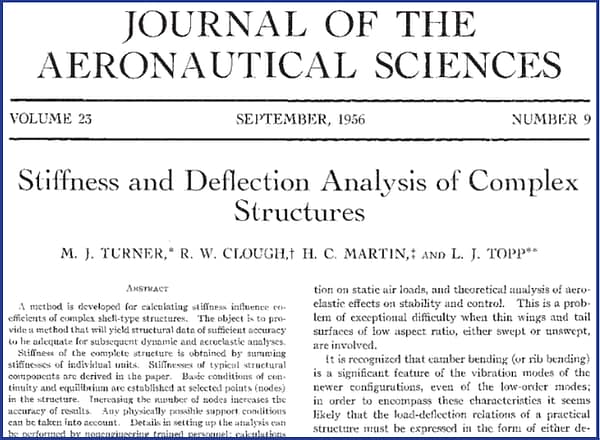
The first paper on the finite element method was published in 1956, and the next year the Soviet Union launched the first satellite (Sputnik) and the space race begun. This brought significant investments into engineering projects in support of the U.S. space program.
In 1965 NASA issued a request for proposal for a structural analysis computer program that eventually led to the development of the finite element analysis software NASTRAN. This marks the beginning of the development of legacy FEA software, and of the practice of finite element modeling.
Early work on developing the FEM was performed largely by engineers. The first mathematical papers were published in 1972. This is an important milestone because mathematicians view finite element analysis very differently from engineers. Engineers think of FEA as a modeling exercise that permits joining various elements selected from a finite element library to approximate the physical response of structural components when subjected to applied loads.
Mathematicians on the other hand, view FEA as a method to obtain approximate solutions to mathematical problems. For example, the equations of linear elasticity, together with the solution domain, the material properties, the loading and the constraints define a mathematical problem that has a unique exact solution which can be approximated by the finite element method.
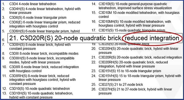
Two main features characterize the early implementation of the emerging technology which lead to the current practice of finite element modeling: (1) large element libraries and (2) the lack of intrinsic procedures for solution verification.

Large element libraries put the burden on the analyst to make appropriate modeling decisions (e.g. why is reduced integration better?)
In 1981 it was proven and demonstrated for a large class of structural problems that the rate at which the error of discretization is reduced when the order of the approximating functions is increased over a fixed mesh, is at least twice as fast as when performing mesh refinement while keeping the order of the approximation functions constant.
In 1984 it was shown that exponential rates of convergence are possible when hierarchic finite element spaces are used with properly graded meshes, which is very significant in the modeling of bodies with cracks. The year 1984 marks the beginning of the development of Numerical Simulation Software (NSS) and of the engineering practice of numerical simulation.
The implementation of hierarchic models began in 1991 in which any mathematical model can be viewed as a special case of a more comprehensive model. This development highlighted the essential difference between numerical simulation software and legacy finite element modeling software.
In legacy FEA software, the mathematical model and the numerical approximation are combined resulting in the development of large element libraries. For example, a QUAD element for linear elasticity, a different QUAD element for nonlinear elasticity, yet another QUAD element for plates, and several variations for each.
In numerical simulation software the mathematical model is treated separately from its numerical approximation. Through the use of hierarchic finite element spaces and hierarchic models it is possible to control numerical errors separately from the modeling errors. As a result there is no need for large finite element libraries or using different element types for different types of analyses. Solution verification is an intrinsic capability for enabling a new generation of numerical simulation software that produces results which are far less dependent on the mesh or the user.
To learn more, watch ESRD’s 5-minute executive summary of the History of FEA and skim our decade-by-decade History of FEA timeline:
Finite Element Modeling Is Not Numerical Simulation
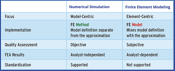
Numerical simulation, unlike finite element modeling, is a predictive computational science that can be used more reliably by both the expert simulation analyst and non-specialist engineer. Thus, a prerequisite for any numerical simulation software product is that it provides quantitative assessment of the quality of the results. Lacking that capability, it still requires an expert to subjectively ascertain if the solution is valid or not, and fails the most basic requirement for solution verification.
Finite element modeling is the practice of breaking the strict rules of implementing the finite element method such that the definition of the model and the attributes of the approximation are mixed, and errors of idealization and discretization are not possible to be separated. The model is re-imagined as LEGO® block connections at nodes using different idealizations and elements that are ambiguously mixed and matched. An example of finite element modeling is connecting 3D solid elements with 1D beam elements (mixing 3D and 1D elasticity). This is a dangerous practice as the model may not have an exact solution and the results will be mesh-dependent.

Numerical Simulation vs Finite Element Modeling: Key Facts
In numerical simulation an idea of a physical reality is precisely stated in the form of mathematical equations. Model form errors and the errors of numerical approximation are estimated and controlled separately. Numerical simulation is the practice of employing properly implemented computational techniques and methods for solving mathematical models discretely. The mathematical model representing the problem “at hand” (i.e., idealization) and the computational techniques employed to solve the mathematical model (i.e., discretization) should always be independent of the idealization. In the practice of legacy finite element modeling the idealization and the discretization are mixed making it impossible to ascertain if differences between predictions and experiments are due to idealization errors, discretization errors or both.
The implementation of hierarchic finite element spaces and models in the latest generation of numerical simulation software is quite different from that of legacy FEA codes, yet there is still confusion among users and software providers alike. When implemented properly, true numerical simulation is most definitely not achieved by adding yet another set of element types to an existing legacy FEA software framework, nor is it pretending that the finite element mesh is hidden. The implementation of hierarchic finite element spaces makes it possible to estimate and control the errors of approximation in professional practice while model hierarchies enable the assessment of the influence of modeling decisions (idealizations) in the predictions, neither one are possible with legacy FEA implementations.

Numerical Simulation supports a simple, hierarchic element library based only on topology
What this means for users is that degrees of freedom are no longer associated with or locked to nodes, design geometry can be mapped exactly without extensive defeaturing, large spanning 3D solid geometries of thin structures typical in aerospace can be modeled using 3D finite elements without simplification, high-fidelity solutions are continuous throughout the domain regardless of the mesh topology, and post-processing now becomes live dynamic results extraction of any function anywhere in the model at any time without a-priori knowledge of the solution required.
Most importantly for the engineering analysis function, numerical simulation software is inherently more tolerant when geometries, loads, or other boundary conditions change due to aerostructure design changes or revised operating conditions. Numerical simulation, unlike finite element modeling, is no longer about selecting the best elements to use or generating the right mesh then getting that mesh right. An objective measure of solution quality for all quantities of interest, combined with hierarchic finite element spaces, enables obtaining accurate results even with low-density “ugly” meshes.
Numerical simulation means that simulation-led design becomes more realistic for aerospace engineering groups, as does the democratization and appification of simulation for non-expert usage. The lack of automatic verification procedures is the most compelling reason to rule out the practice of finite element modeling in the creation of simulation apps that attempt to democratize the use of simulation.
Coming Up Next…
In the next S.A.F.E.R. Simulation post we will describe how the practice of Simulation Governance, enabled by a new generation of engineering analysis software based on Verifiable Numerical Simulation (VNS), such as ESRD’s StressCheck, is helping engineering groups respond to an avalanche of increasing performance, interdependent complexity, and technical risk in their products, processes, and tools. And this, in the process, makes structural analysis of aerostructures using finite element numerical simulation software more Simple, Accurate, Fast, Efficient, and Reliable for the new and expert user alike.
 Serving the Numerical Simulation community since 1989


Leave a Reply
We appreciate your feedback!
You must be logged in to post a comment.